UTAT Rocketry Avionics Lead
Led 60+ students to deliver 39 custom PCBs (26 personal designs). Established Altium standards, mentored engineers, and spearheaded RF, power, and thermal validation.
UTAT Rocketry Avionics Lead
Technical focus
- Lead avionics systems across propulsion, recovery, and airframe with stackups, interfaces, and integration planning.
- Own schematics/layout for power, safety, and test boards while managing firmware handoff and bring-up.
- Set DFM/DFT rules for impedance control, return paths, power budgets, and library standards in Altium.
- Run reviews, mentoring, and bench validation (oscilloscope, thermal, RF tests) for the complete avionics systems on our Discovery rocket.
Results
- 39 unique boards designed/reviewed, 20+ fabricated/assembled/tested, multiple subsystems flown to 10k ft.
- Personally designed 26 PCBs and collaborated on 13 others since mid-2024 while mentoring 60+ students with 10-15 engineers per session.
- Spearheaded extensive oscilloscope debugging, thermal and electrical validation, and RF testing.
- Standardized interfaces, libraries, and sponsorship outreach to keep avionics and power timelines on track.
Stack
Since mid-2024, I have served as the Avionics Lead for UTAT, mentoring over 60+ students in electronics design and embedded systems, with an average concurrent meeting attendance of 10-15 engineers.
In this capacity alone, on top of other personal projects I have personally designed 26 PCBs, collaborated on 13 others, and provided critical design reviews and assembly assistance for 39 unique boards with UTAT Rocketry. I also drove team-wide standardization and library management, systems planning, and interface management across subteams like propulsion, recovery, and airframe.
I have also done extensive bench testing with oscilloscopes and thermal imaging, firmware integration (including writing firmware myself), represented the team at events, recruited new members, and secured sponsorships by reaching out to companies.
See My PCBs
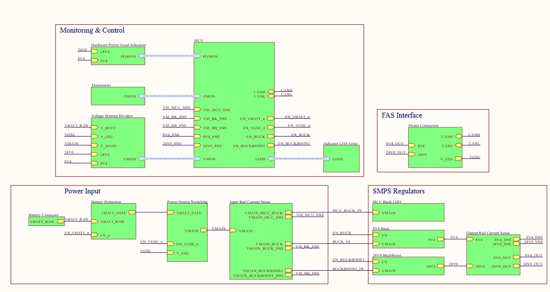
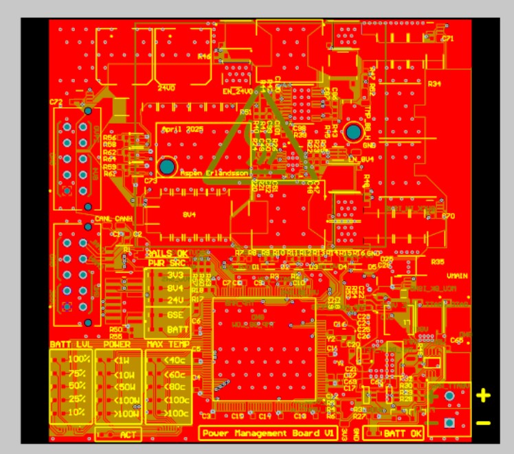
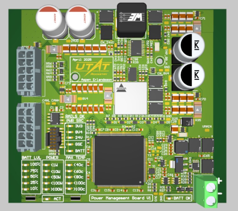
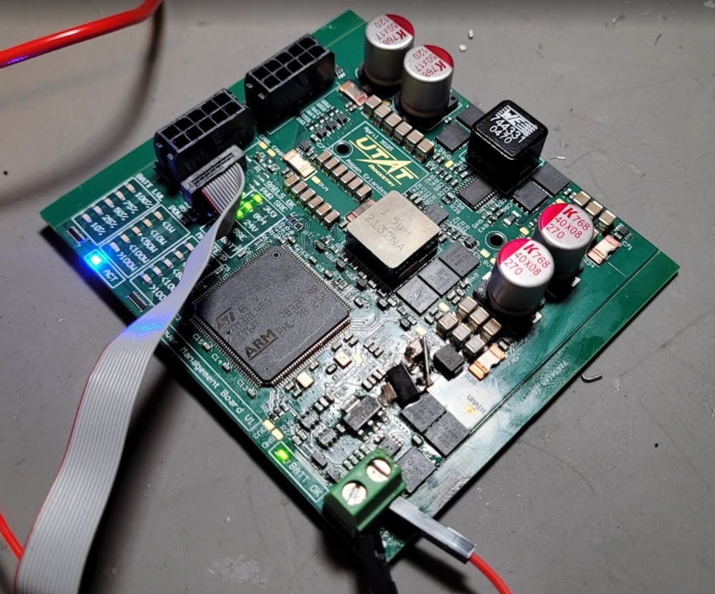
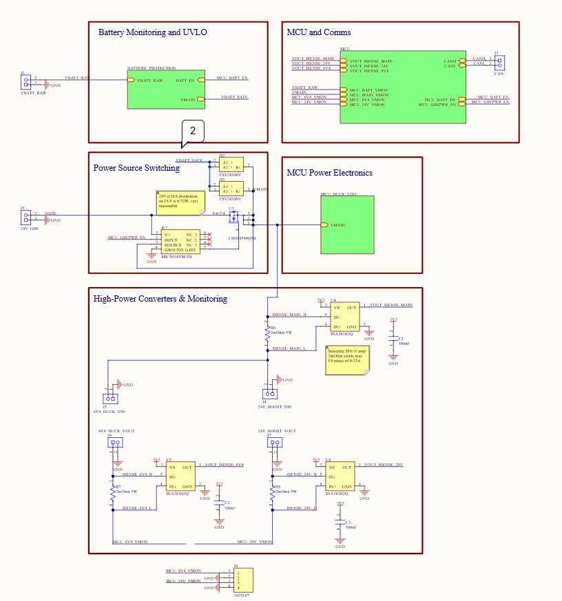
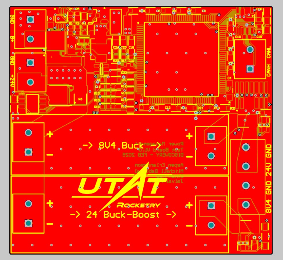
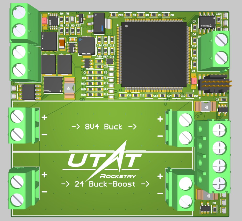
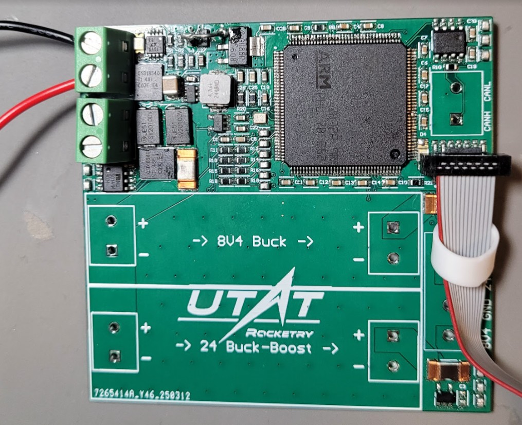
Power Management Board V1
The primary power distribution unit for Discovery. Integrates a 20A buck converter (Battery->8.4V), a buck-boost (Battery->24V), and hot-swap logic for switching between internal and ground power. Features UVLO/OV protection, current/voltage monitoring, and an STM32-controlled LED debug array.
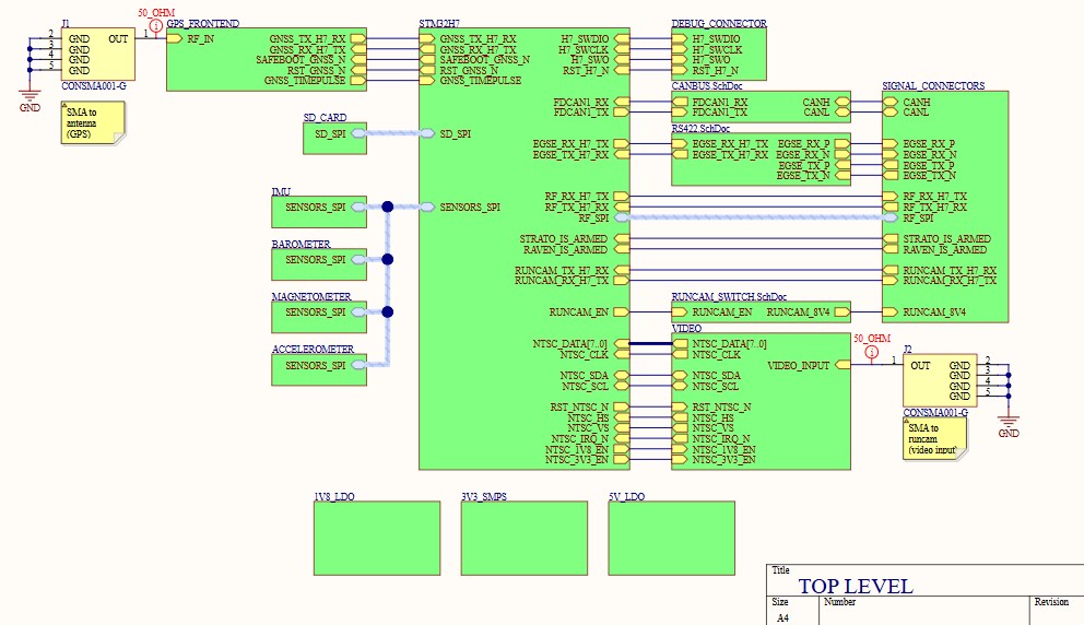
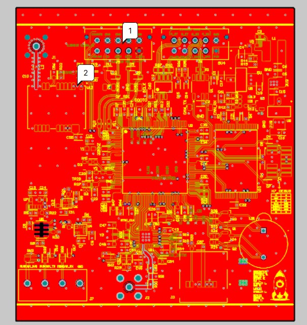
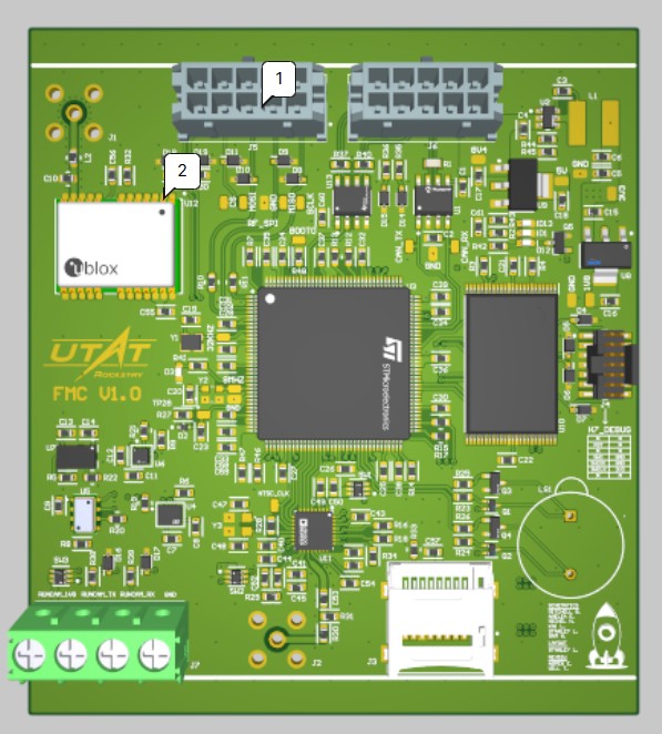
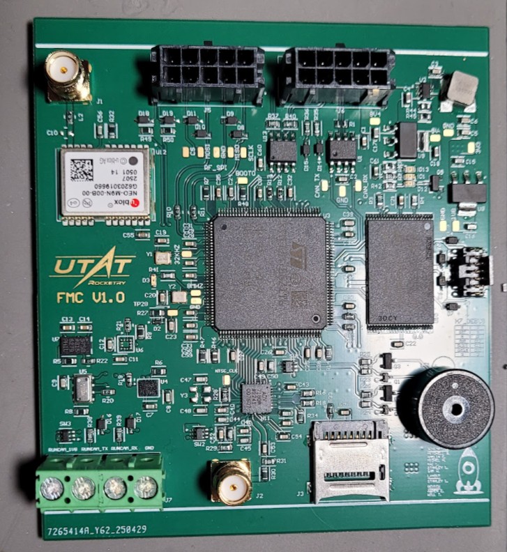
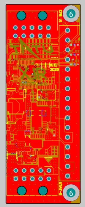
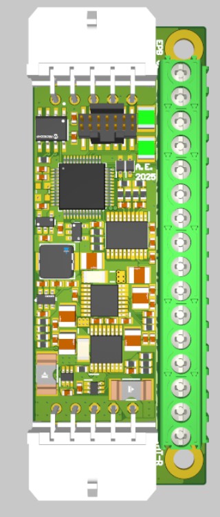
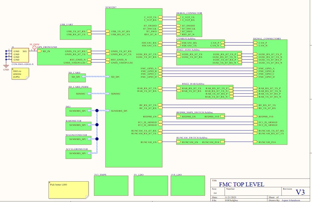
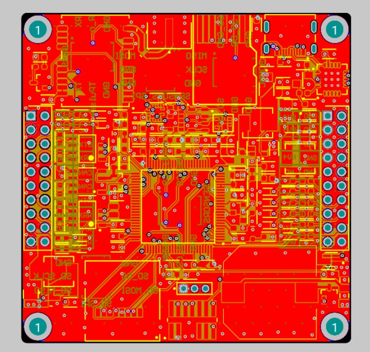
Flight Management Computer V1
The core processor for the Discovery rocket. Features a dual-core STM32H755 on a 6-layer stackup, integrating onboard GPS, IMU, high-G accelerometer, barometer, SD card, Flash, and experimental video streaming hardware.
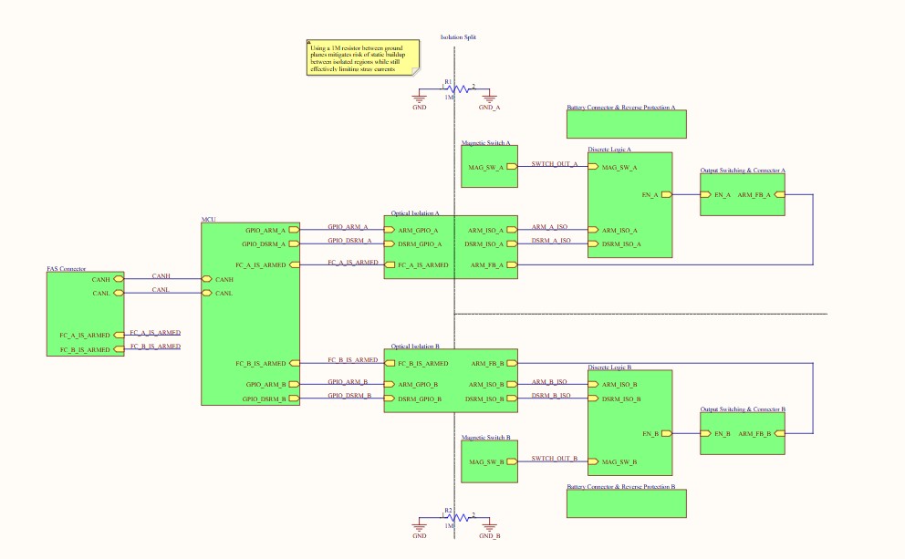
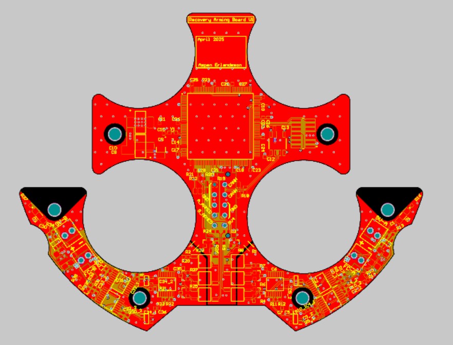
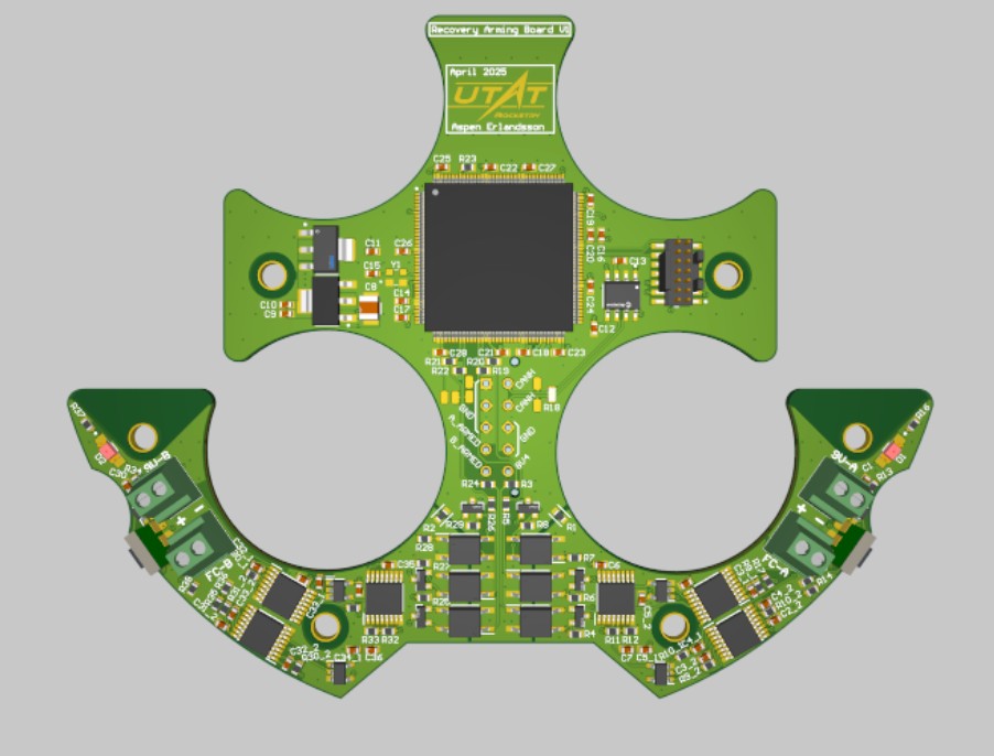
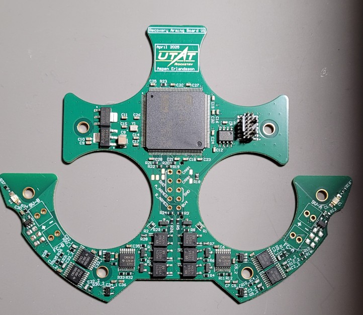
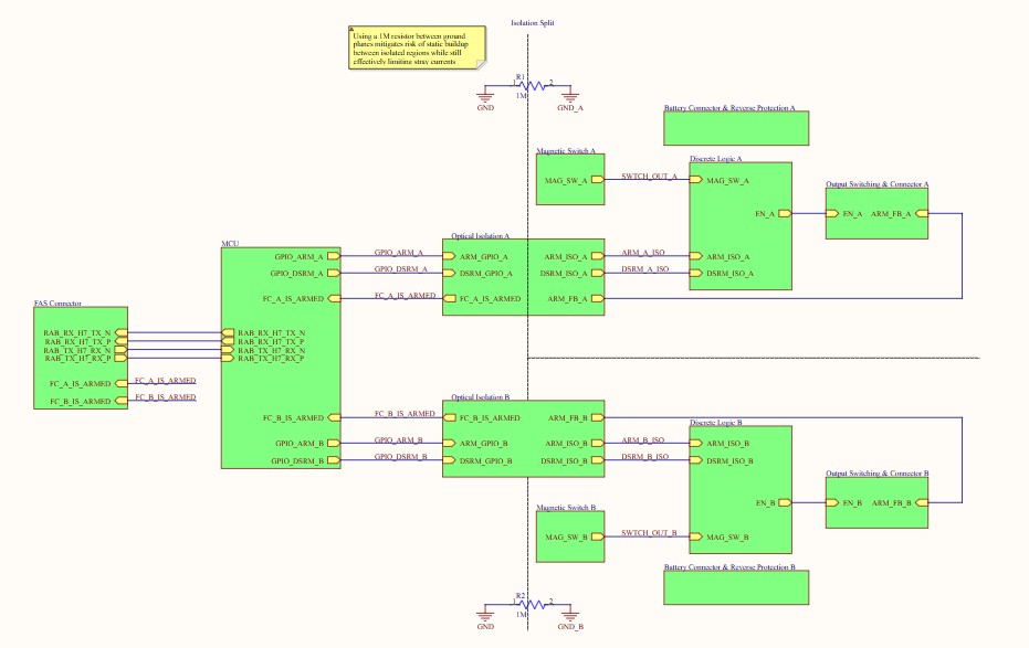
Recovery Arming Board V1
Interfaces with the avionics system to provide arming/disarming capability for parachute deployment. Features fully redundant dual-path magnetic arming through the airframe using galvanic isolation.
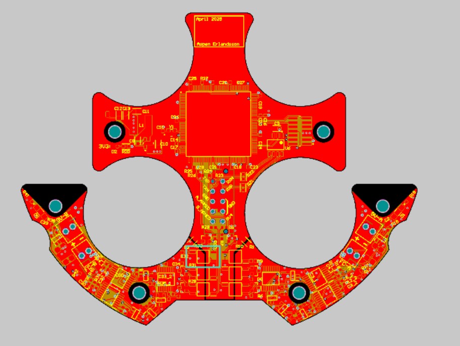
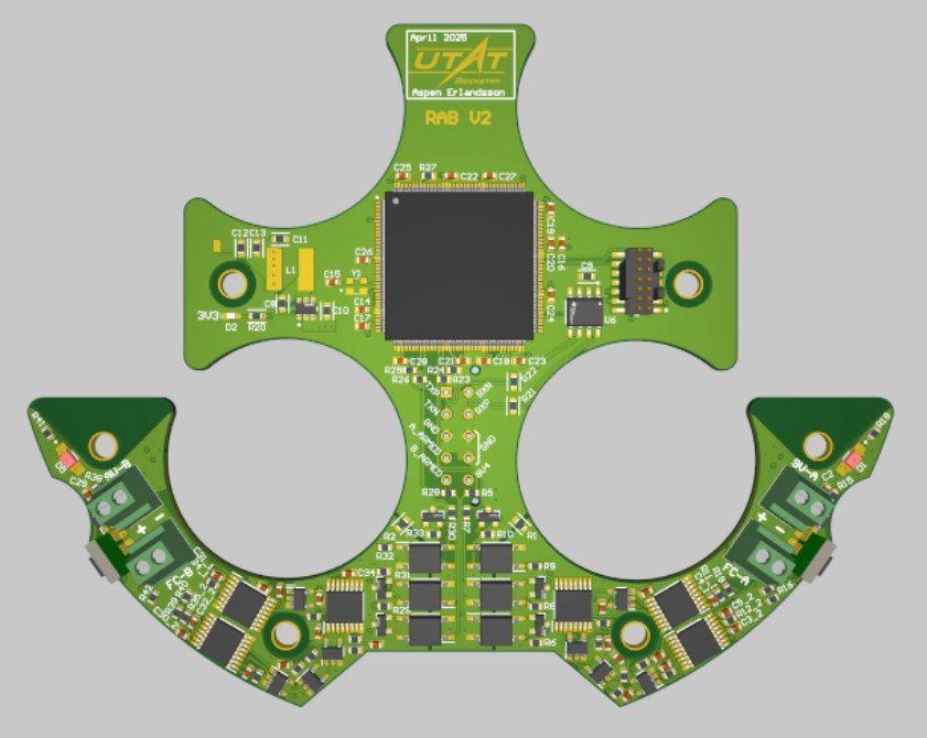
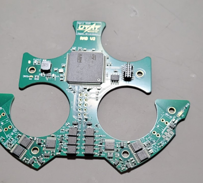
Recovery Arming Board V2
Iteration on V1 addressing quiescent power draw issues and high-load voltage drops by optimizing the FET gate drive setup. This version successfully flew to 10,000 ft on the Enterprise solid rocket.
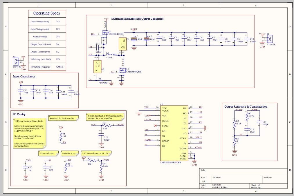
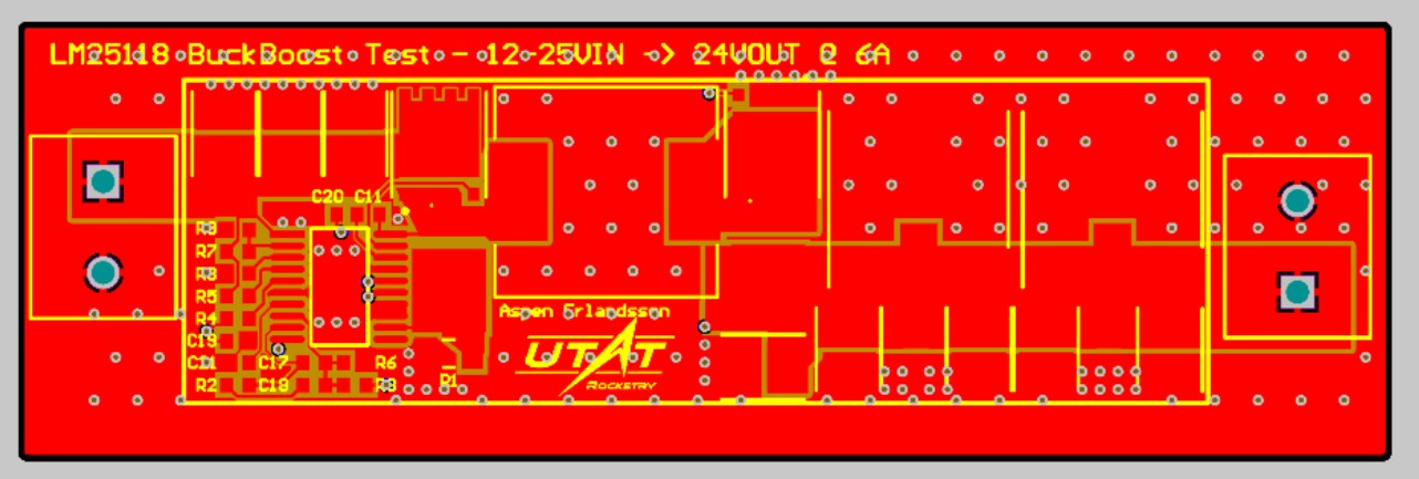
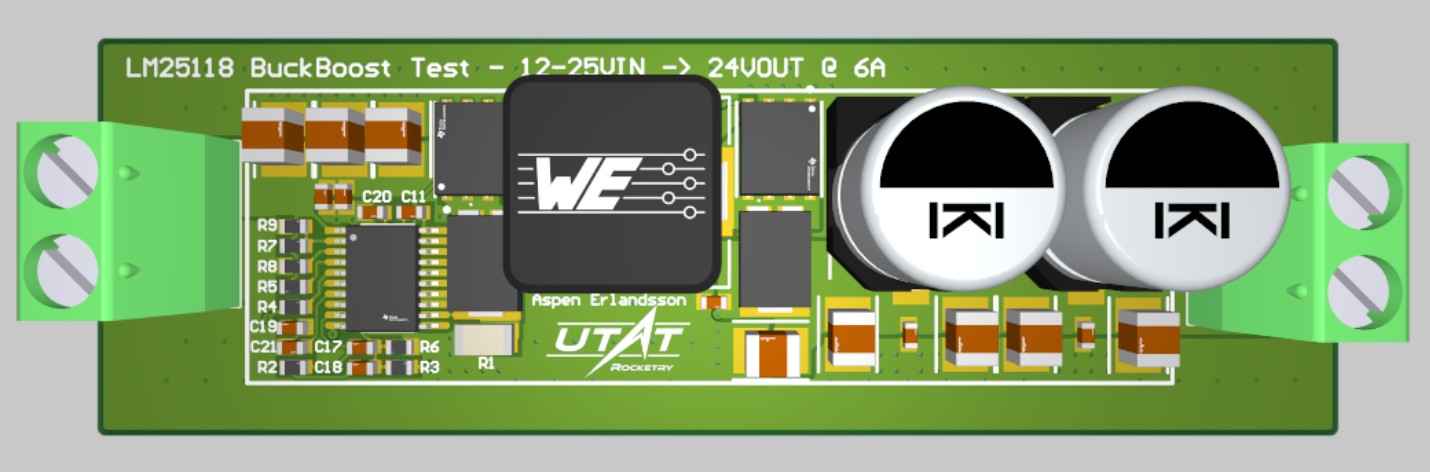
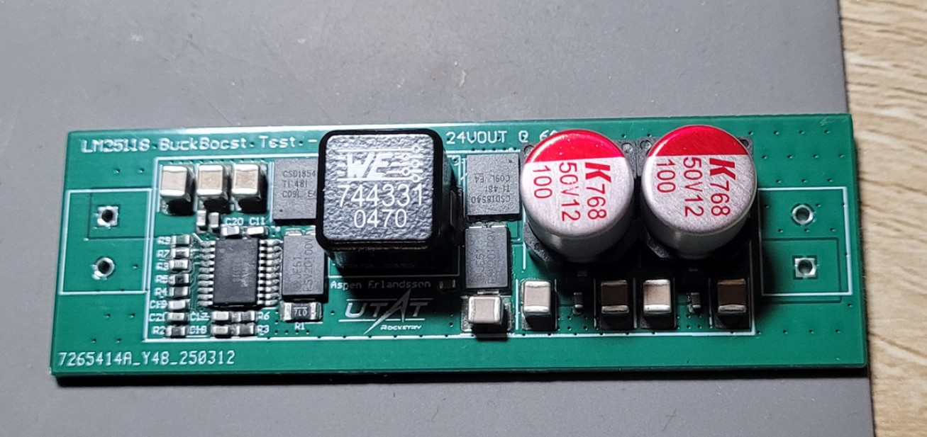
LM25118 Boost EVM
Test board for the PMB converter setup. Converts 12-25V input to a regulated 24V output at 6A max. Features a 4-switch asynchronous design with current limiting and spread spectrum operation for reduced EMI.
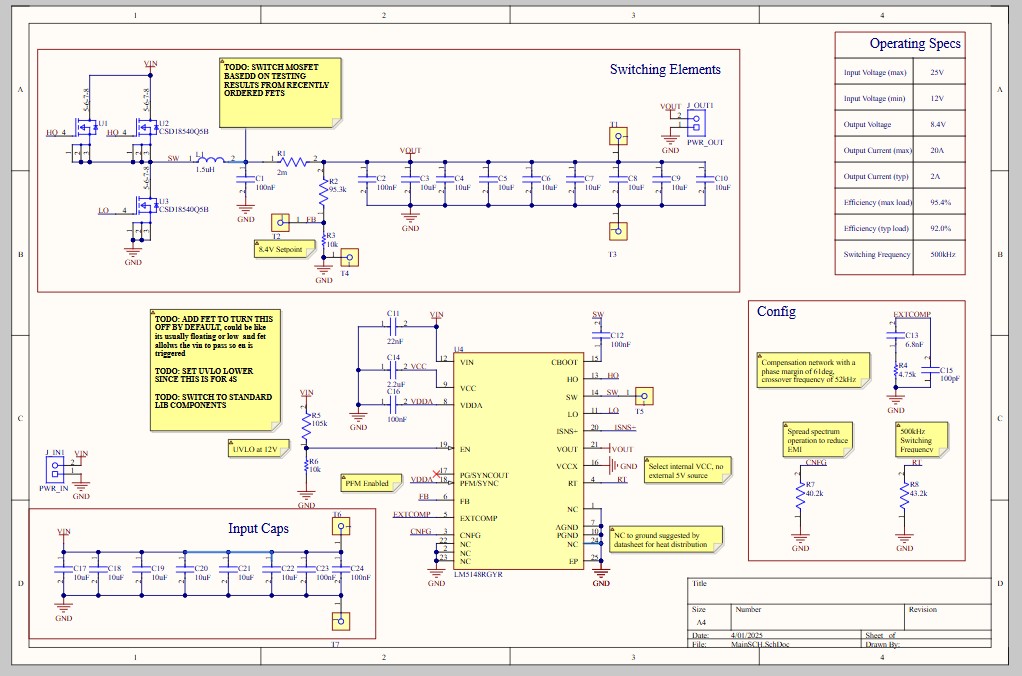
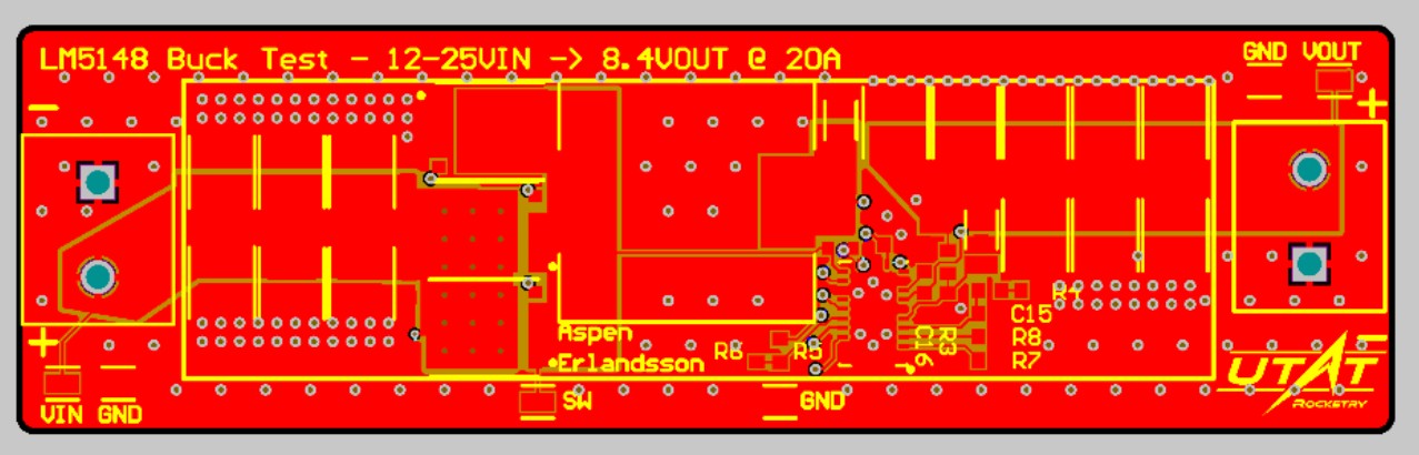
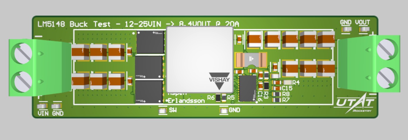
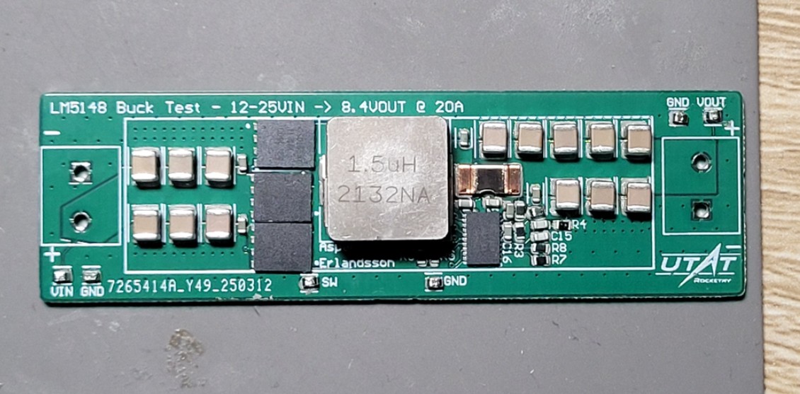
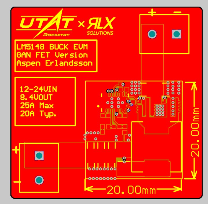
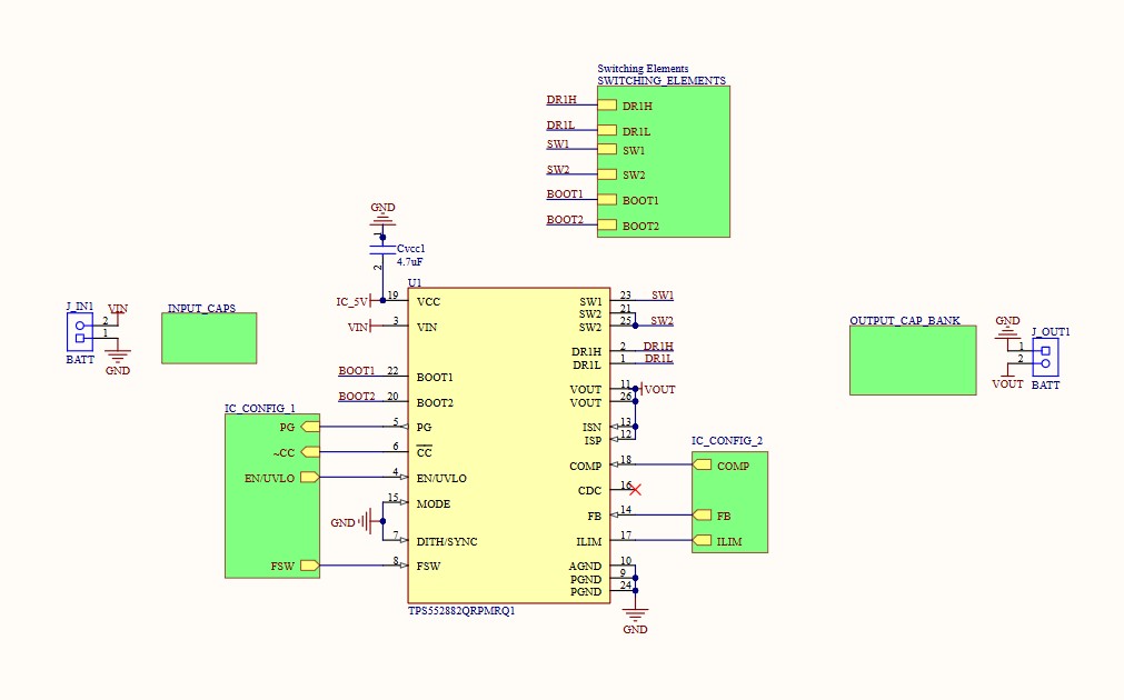
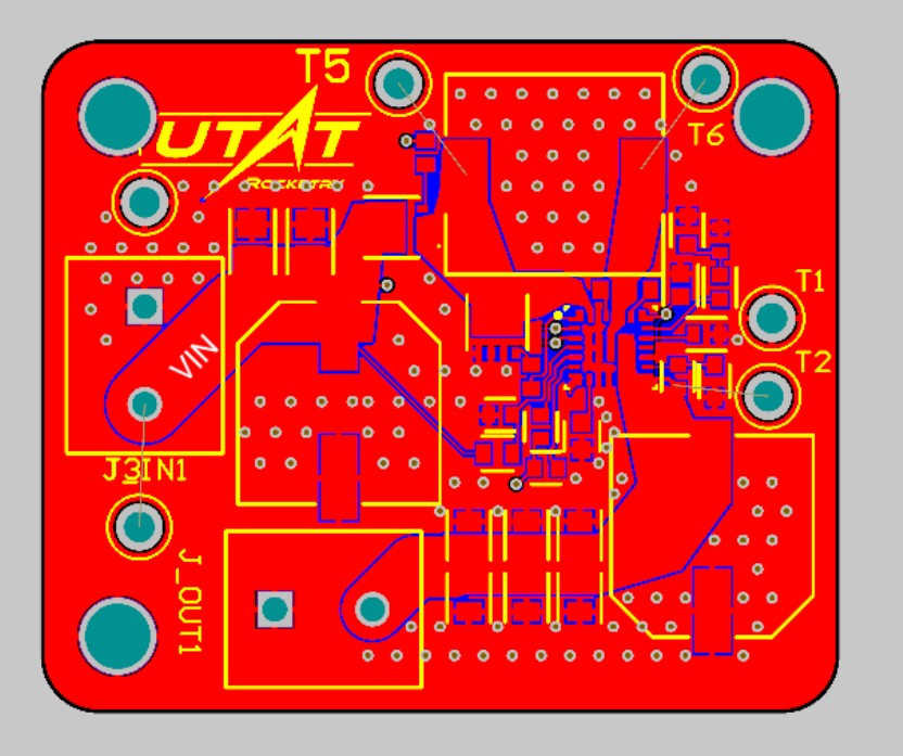
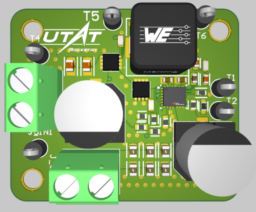
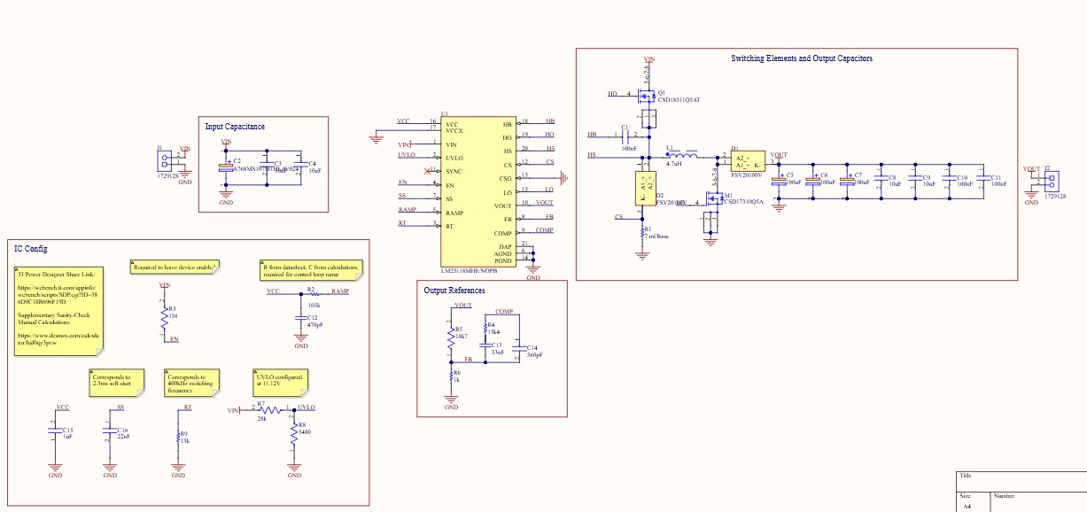
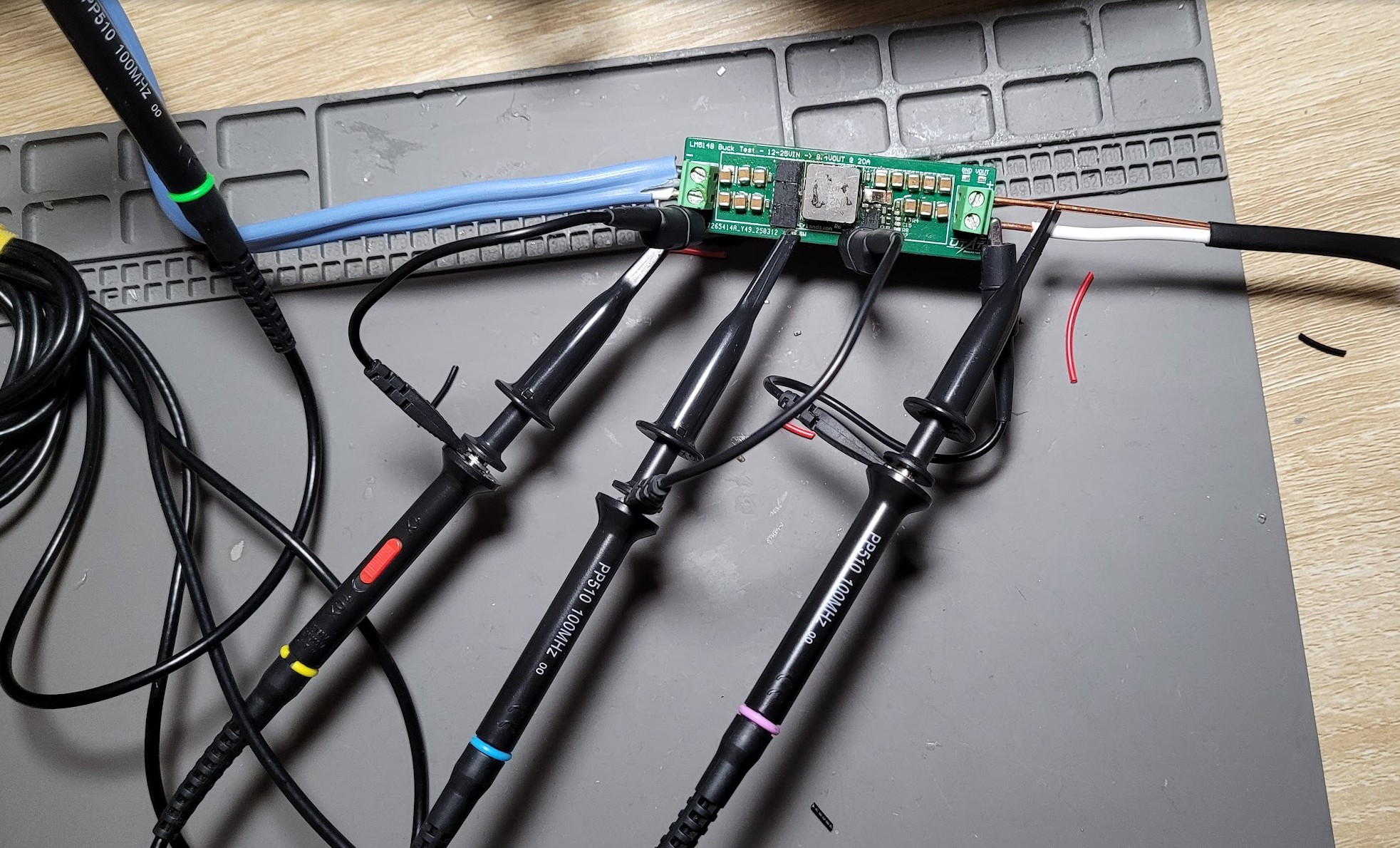
LM5148 Buck EVM
High-current buck converter test board converting 12-25V input to 8.4V output at 20A max. Designed with multiple onboard test points for electrical and thermal validation.
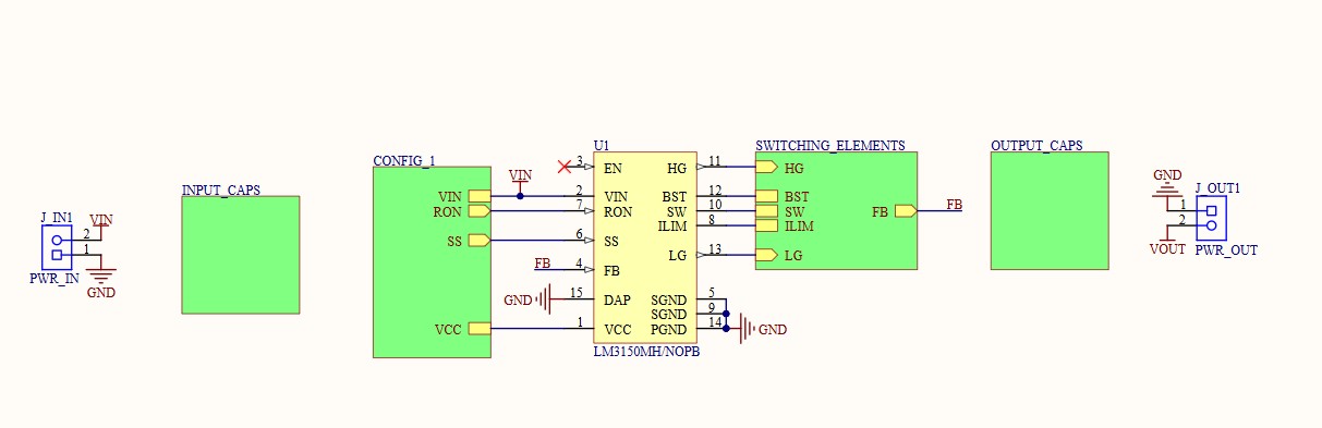
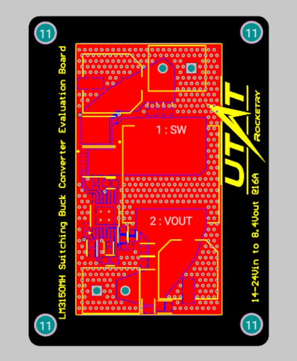
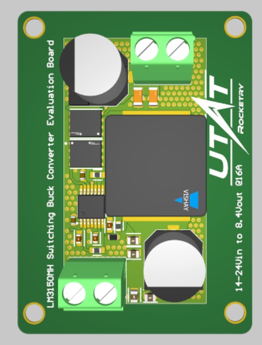
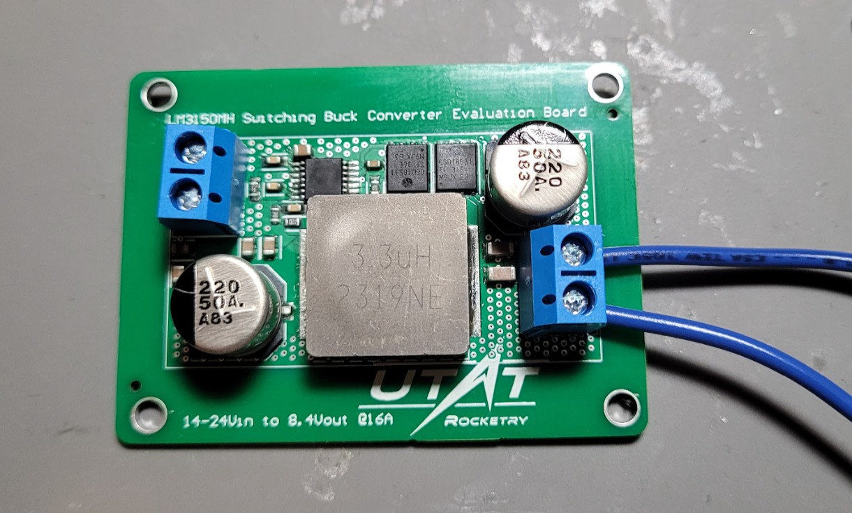
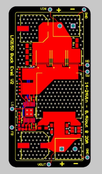
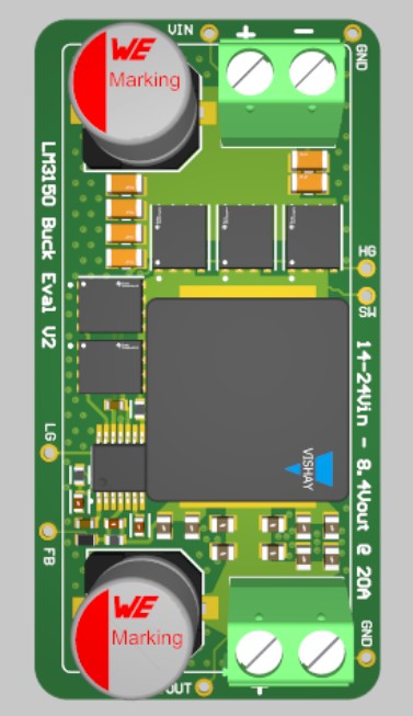
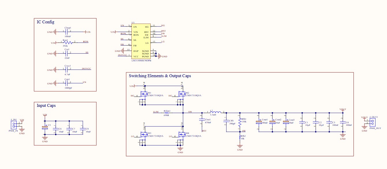
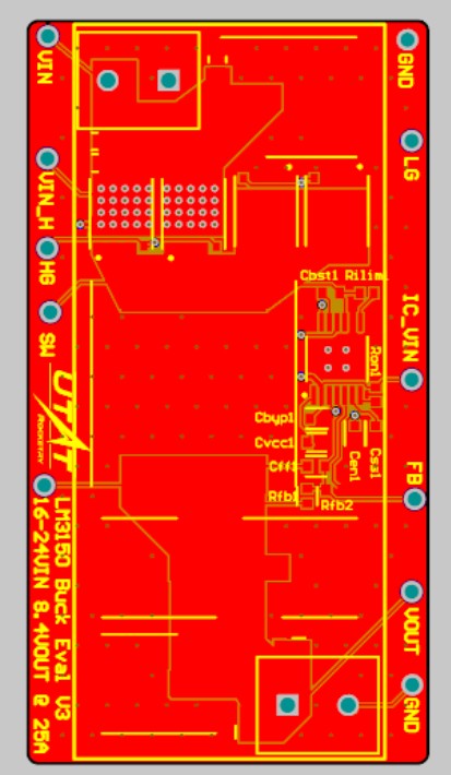
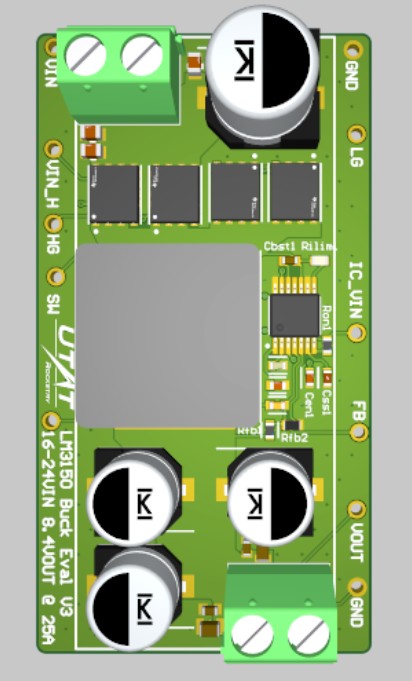
LM3150MH Buck EVM
Initial buck converter prototype targeting 16A. Functioned correctly up to 12A but saw thermal throttling beyond that, driving the V3 iteration.
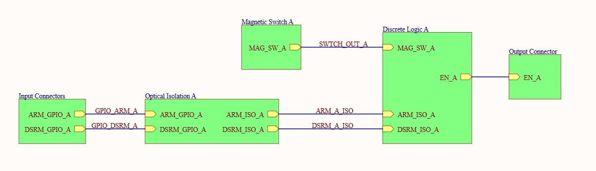
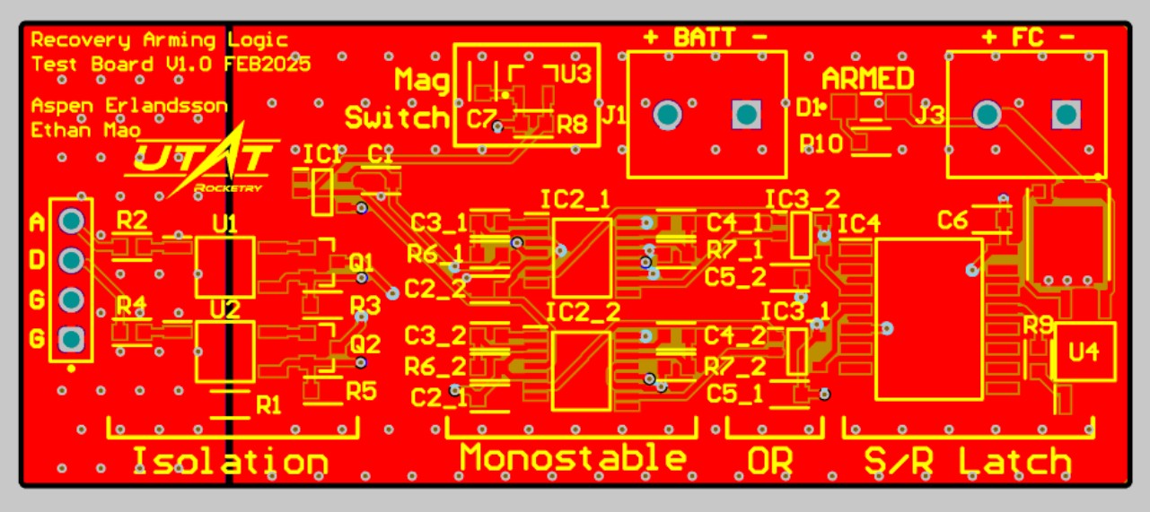
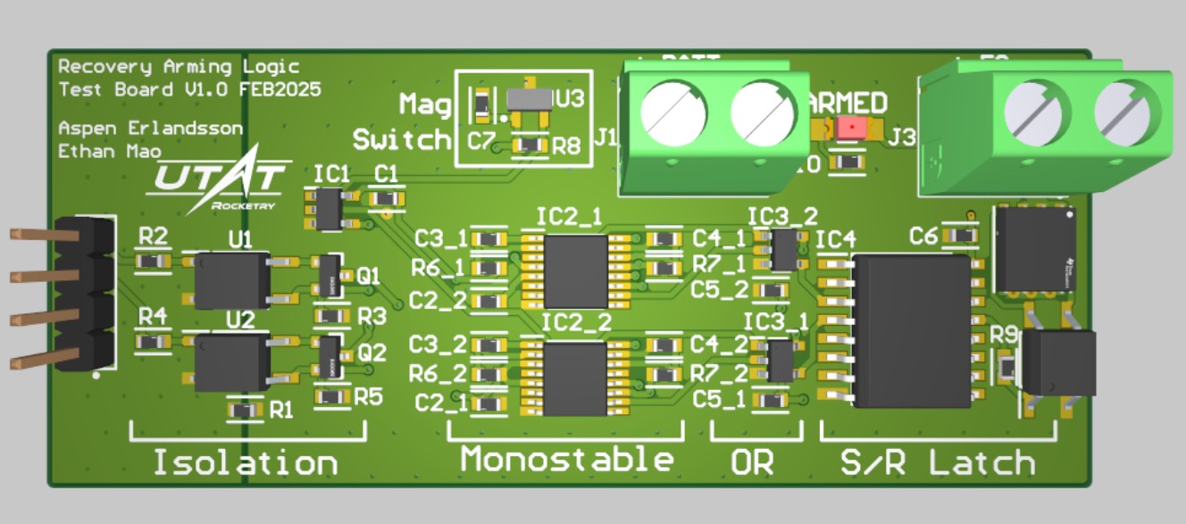
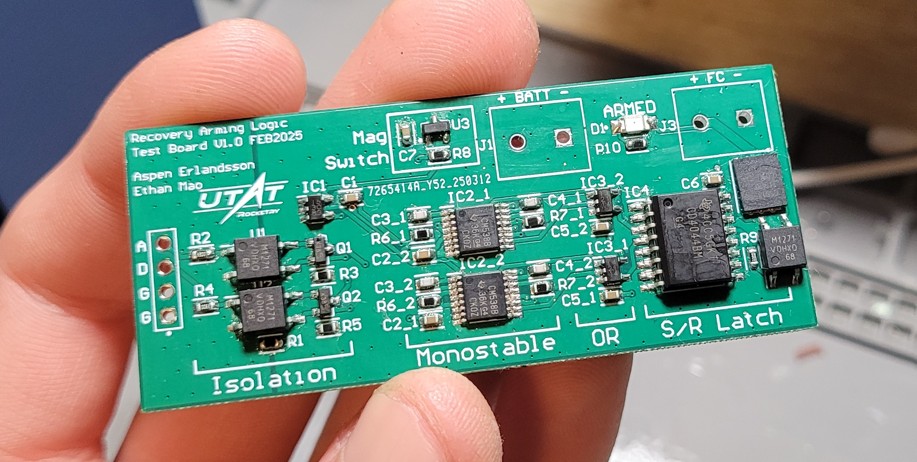
RAB Logic Test Board
Early prototype for the RAB dual-redundant arming logic using multiple discrete monostable components to avoid microcontrollers in safety-critical paths.
PMB Logic Test Board
Validation board for battery protection, hot-swap logic, and current/voltage monitoring. Also served as a testbed for our STM32L4 selection and debug connector standards.
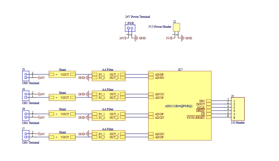
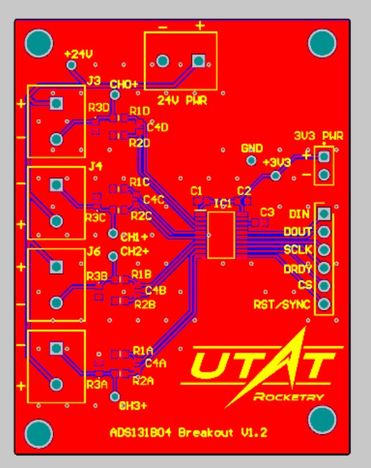
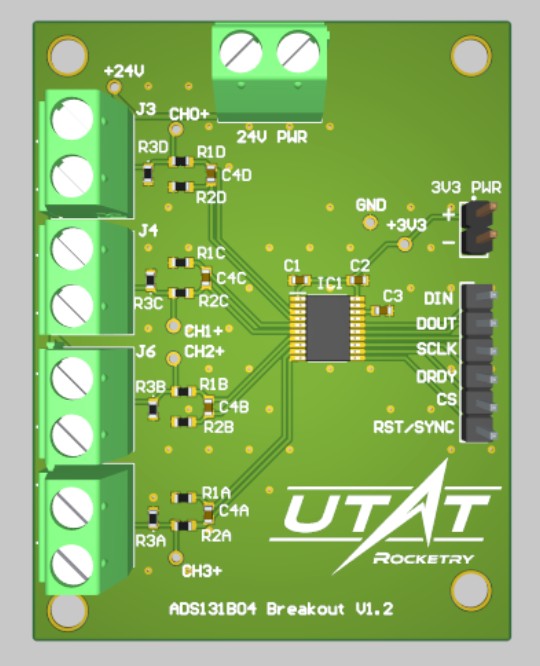
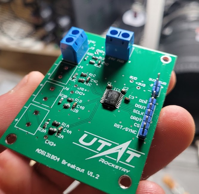
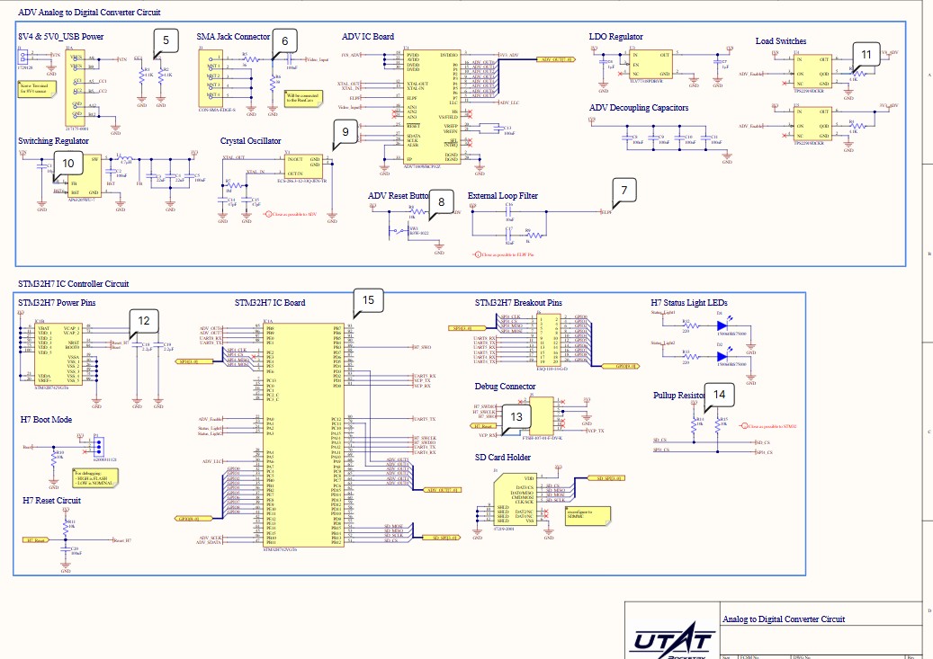
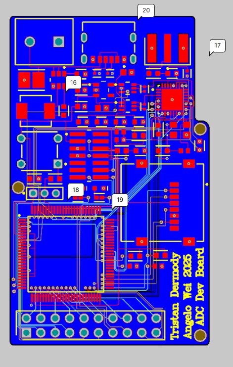
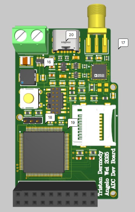
ADS131B04 Breakout
Breakout for a 24-bit 32ksps sigma-delta ADC with low-pass filters on differential inputs. Used for firmware development and performance evaluation.
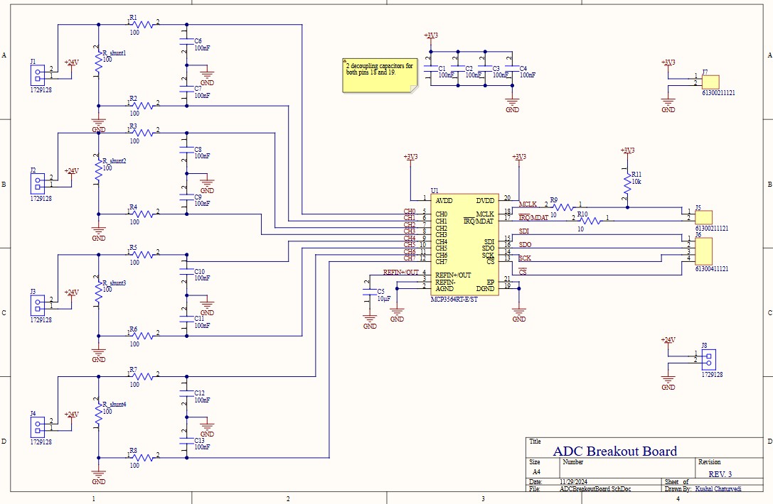
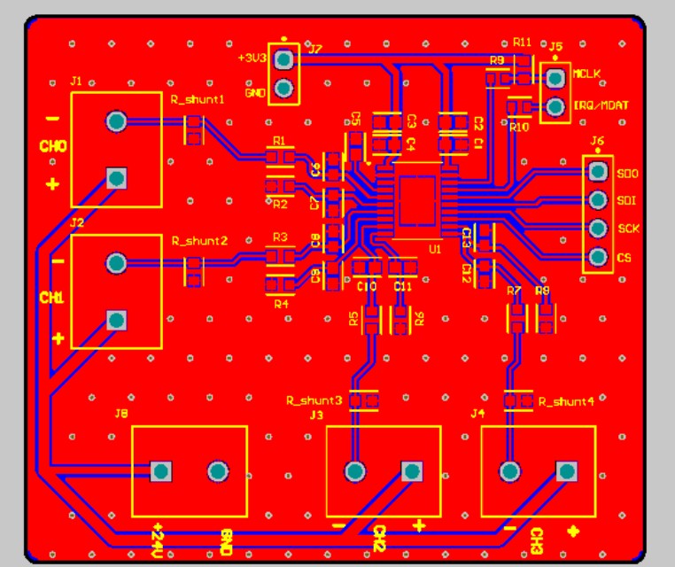
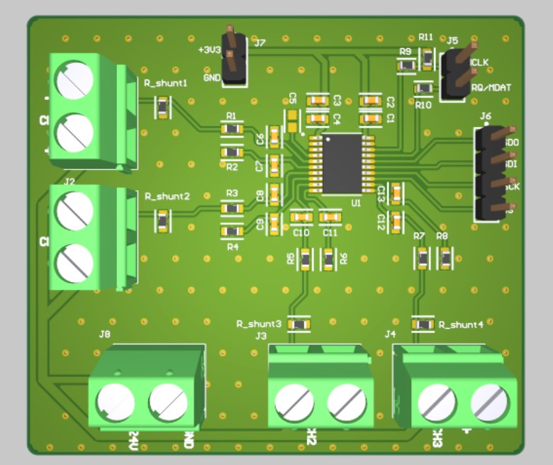
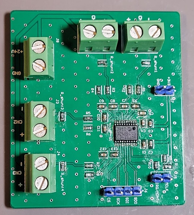
MCP3564RT Breakout
4-channel sigma-delta ADC breakout board with low-pass filters on differential inputs.
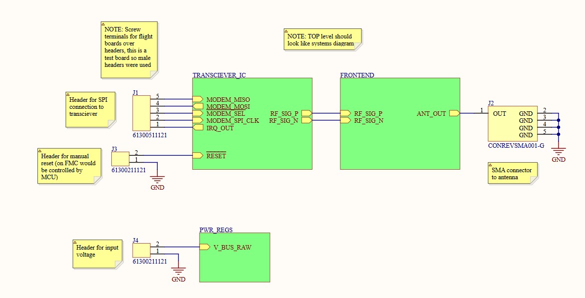
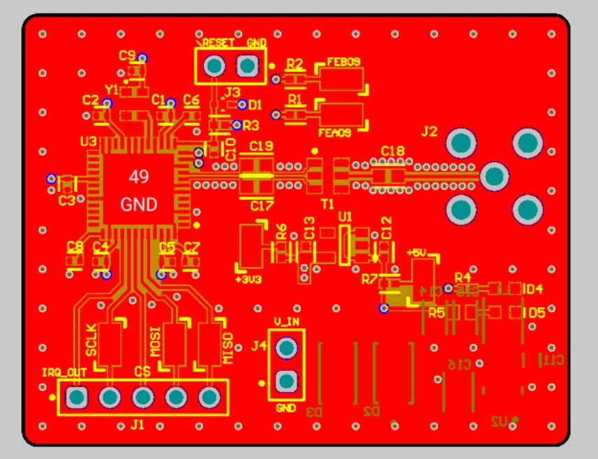
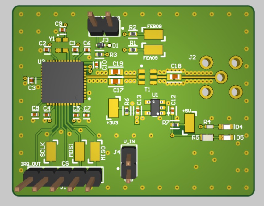
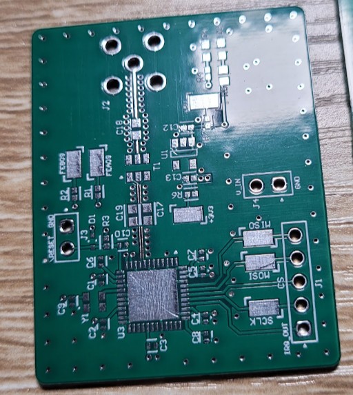
915MHz Transceiver Breakout
Breakout board for a 915MHz RF Transceiver used in our in-house telemetry project.
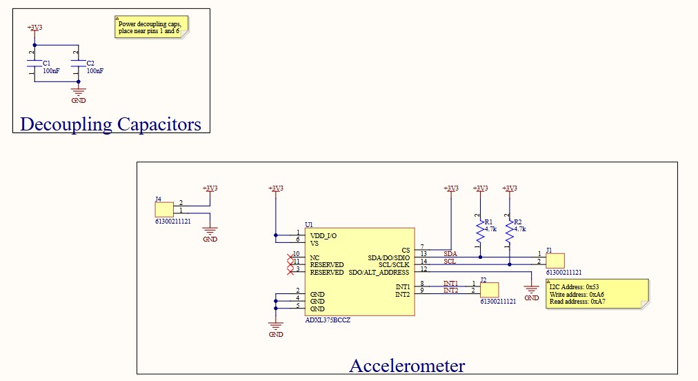
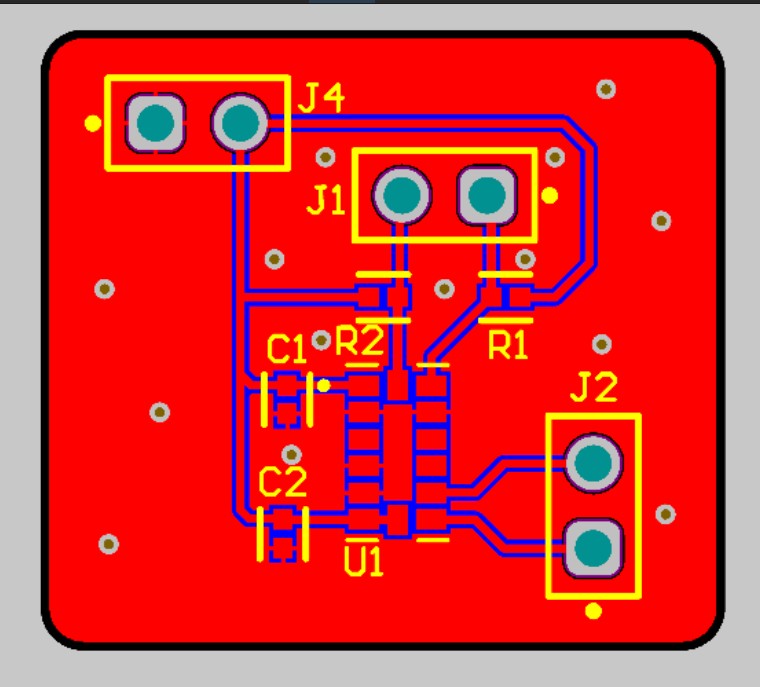
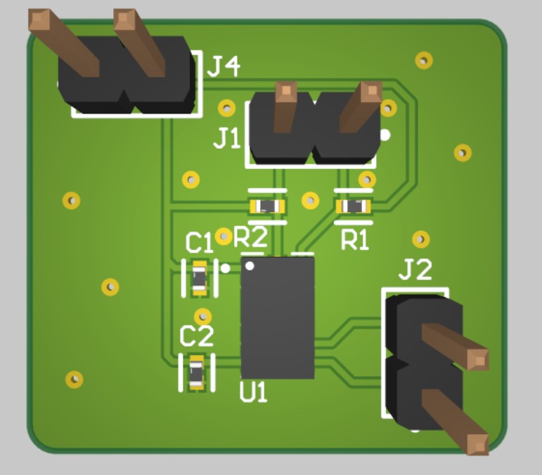
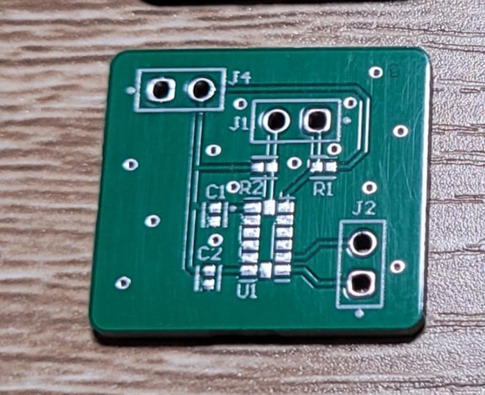
High-G Accelerometer Breakout
ADXL375 high-G (200G) accelerometer breakout board for firmware development.
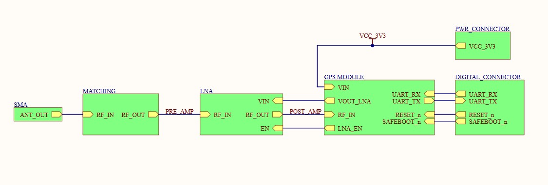
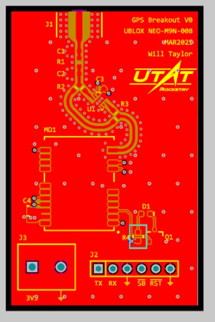
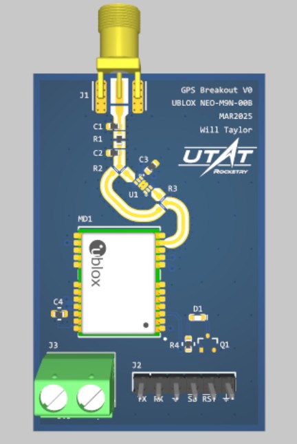
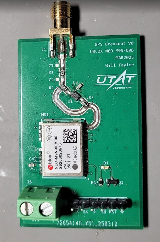
GNSS Breakout
UBLOX NEO-M9N GPS module breakout board for firmware development and performance evaluation.
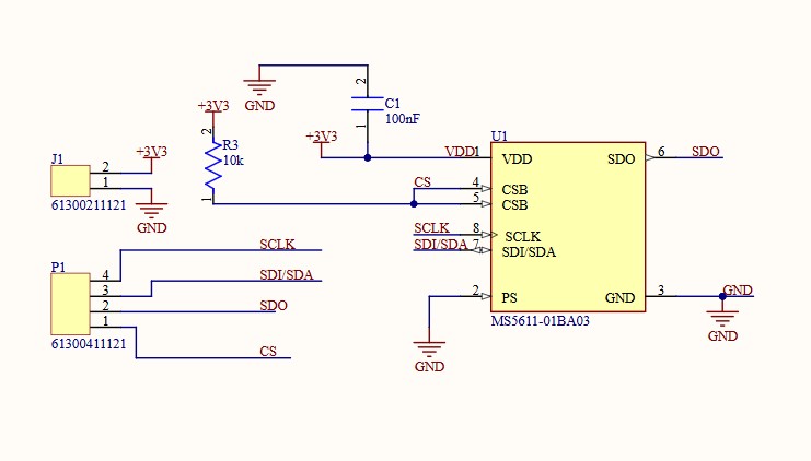
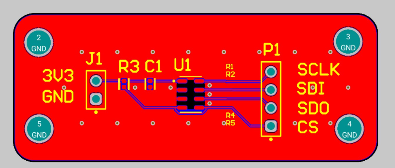
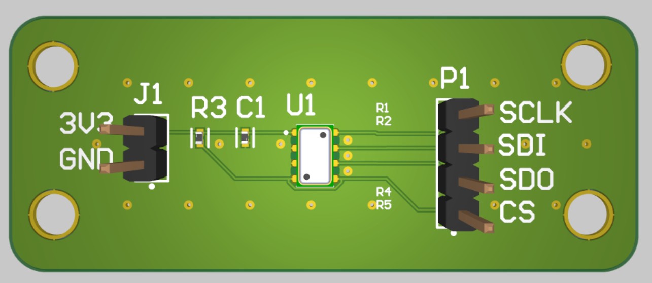
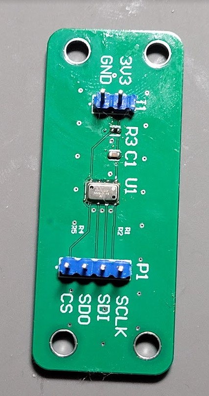
Barometer Breakout
MS5611 Barometer breakout board for firmware development and performance evaluation.
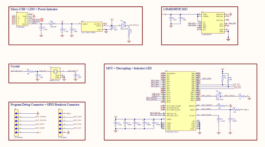
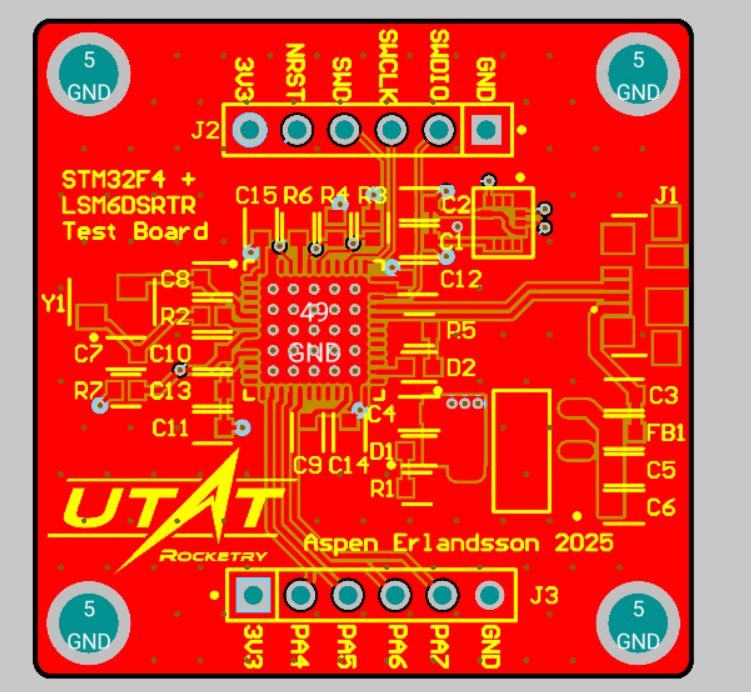
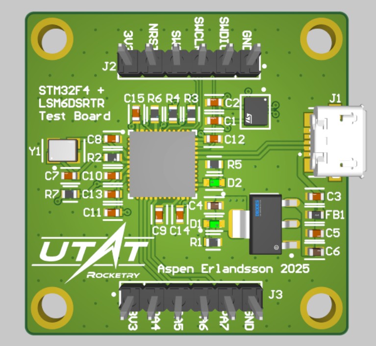
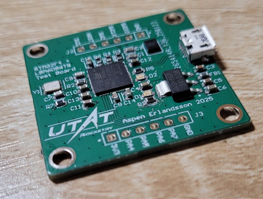
STM32F4 Development Board
Custom development board to validate clock topology, IMU integration, and gain experience with the STM32 ecosystem.
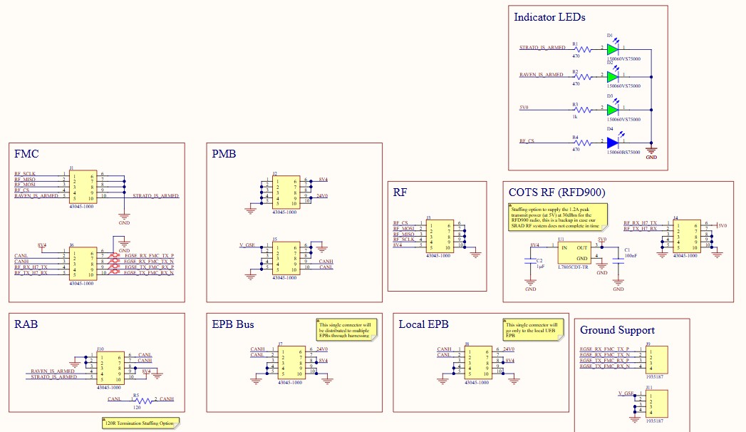
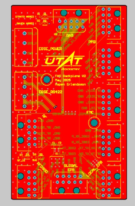
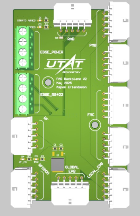
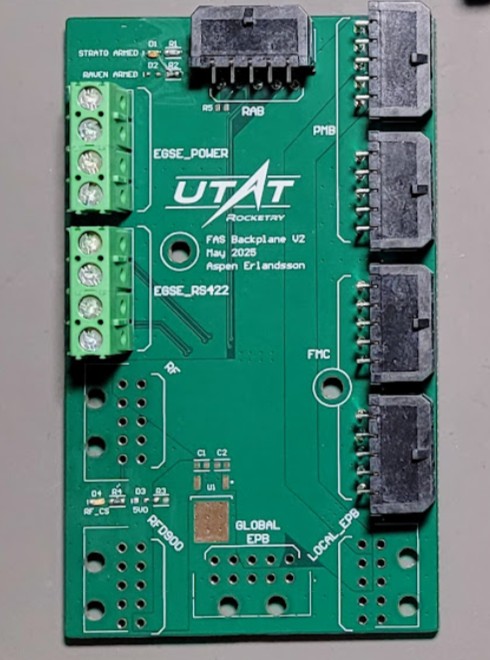
Avionics Backplane V2
Central interconnect for the Flight Avionics System (FAS) using vibration-resistant Molex connectors and high-current power traces. Optimized size compared to V1.
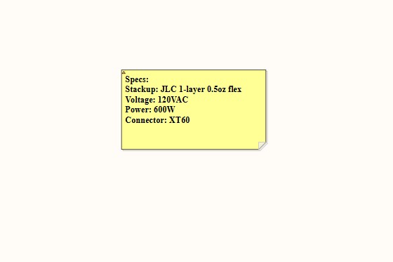
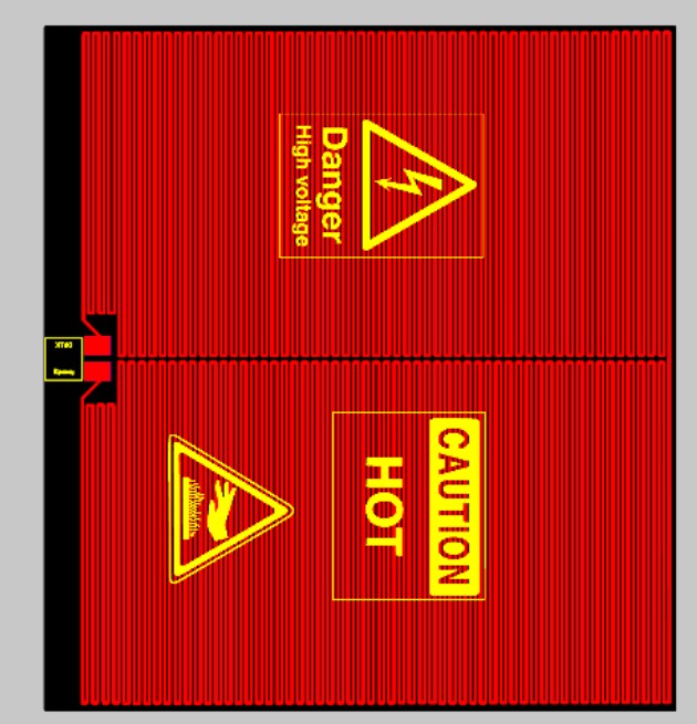
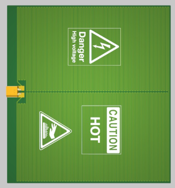
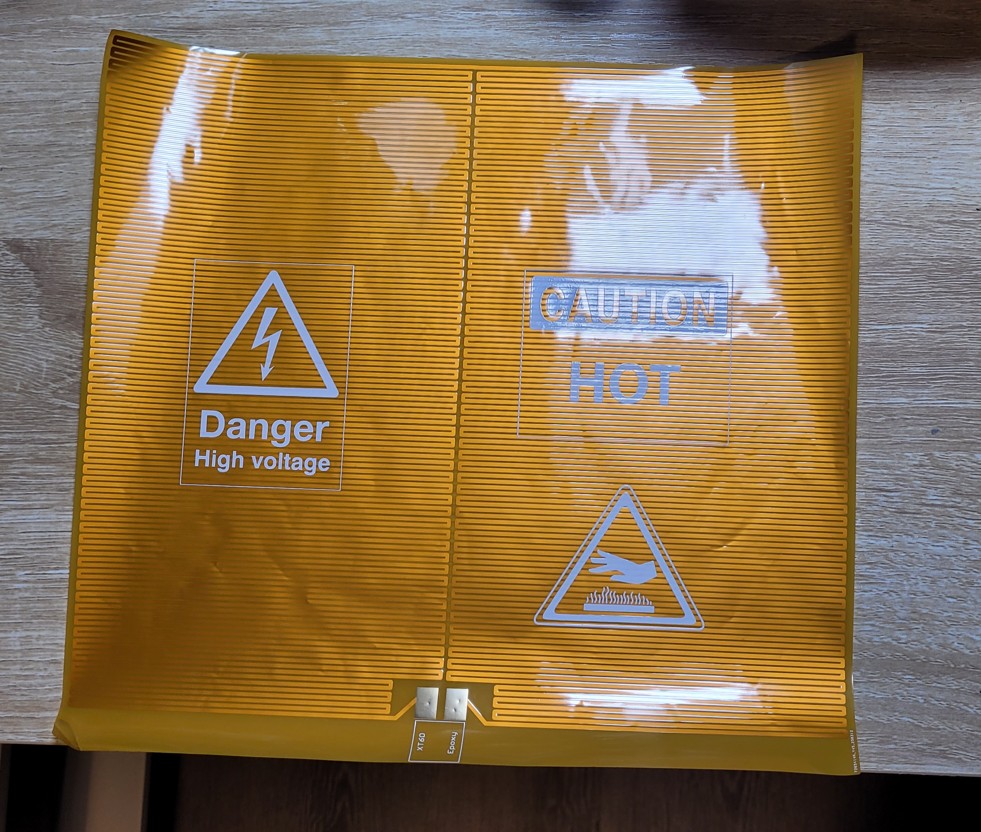
Tank Heater PCB
Flexible polyamide PCB designed as a 600W/120VAC resistive heater. Wrapped around the oxidizer tank to prevent valve freezing during cold fills.
Magnetic Arming Daughterboard
Vertical riser board that solders onto the RAB, ensuring the magnetic sensor is oriented correctly relative to the airframe surface.
Avionics Backplane V1
Initial concept for the central avionics interconnect. Provided valuable lessons on mechanical fit and connector selection.
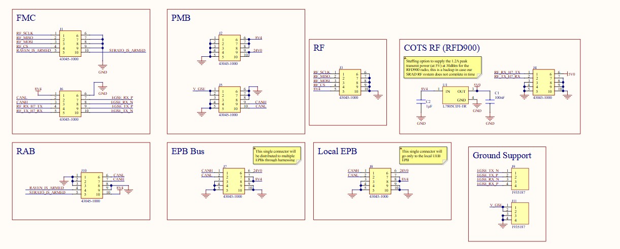
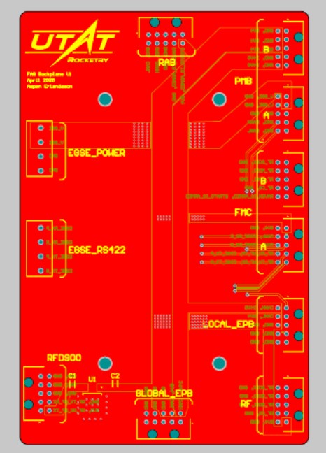
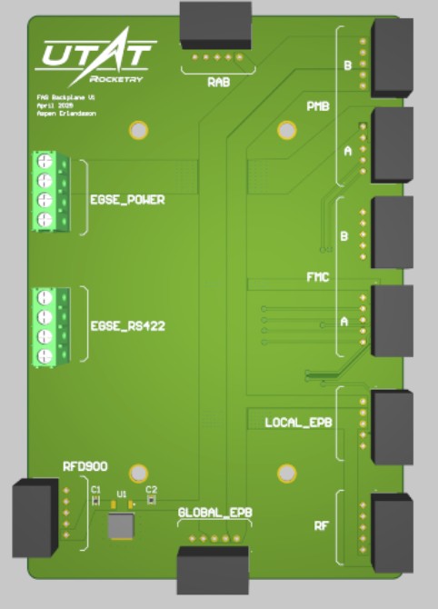
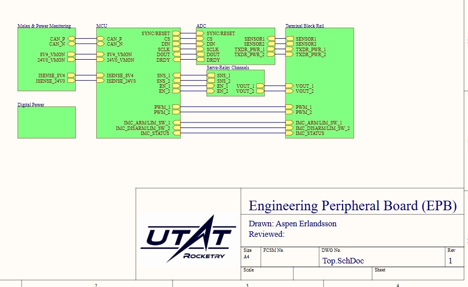
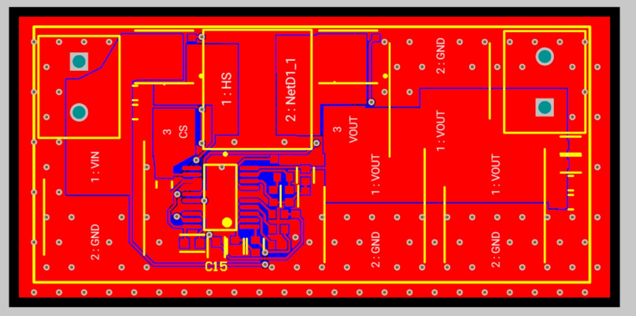
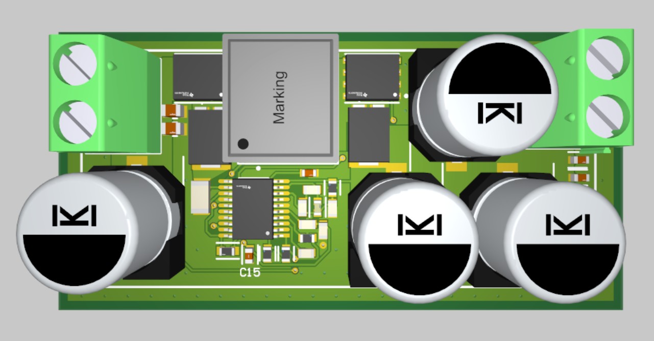
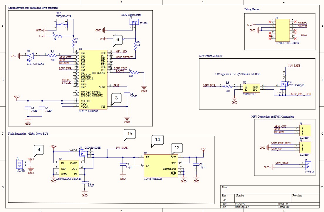
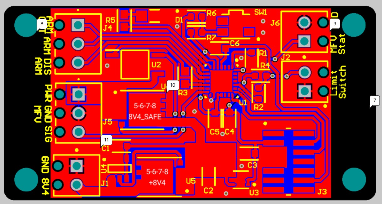
Engineering Peripheral Board V1
Compact distributed node controller. Integrates STM32G0, FDCAN, and solenoid/servo control to manage propulsion actuators and read sensors.
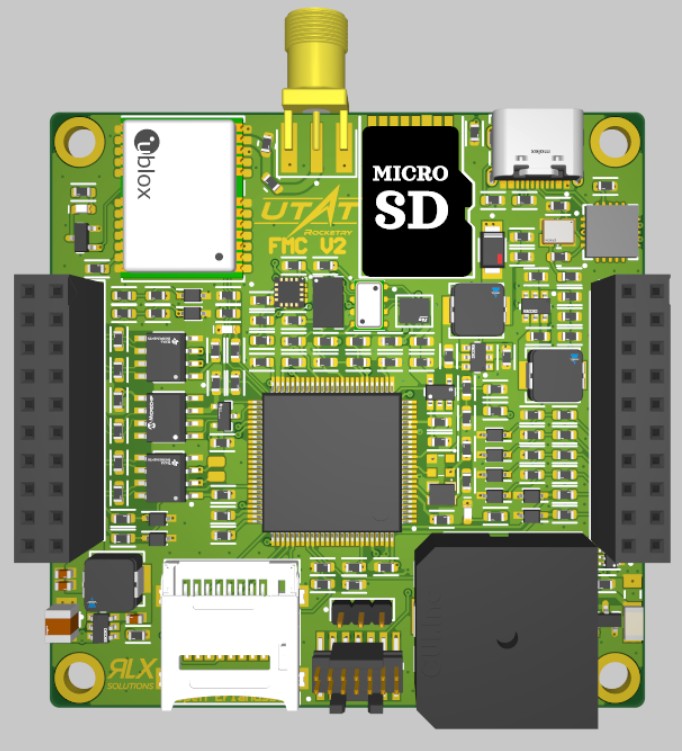
Flight Management Computer V2
Compact (60x60mm) iteration of the FMC to support smaller airframes. Features 6-layer impedance controlled stackup, USBC for power/serial, onboard power management, compact buzzer, and redundant SD cards.
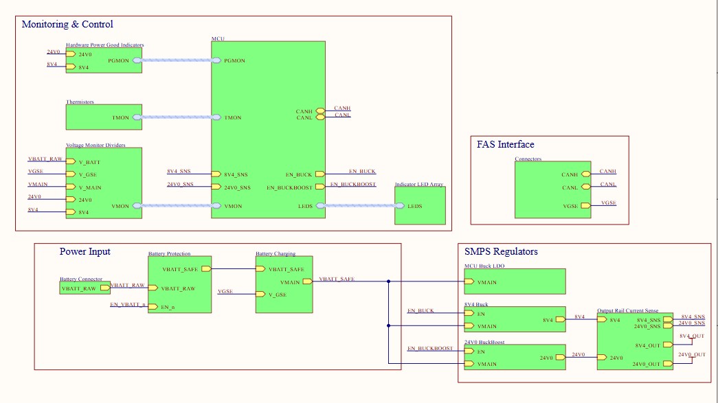
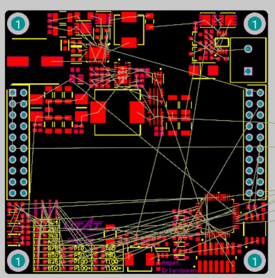
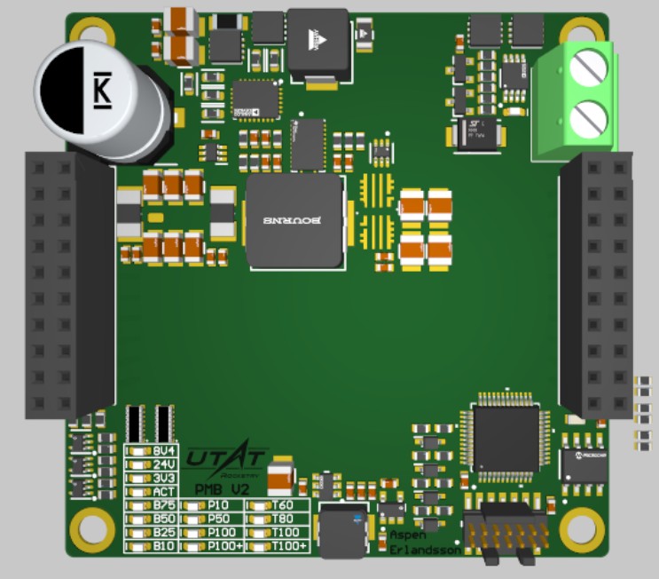
Power Management Board V2
Next-gen PMB integrating results from Buck/Boost EVMs into a 60x60mm footprint. Features optimized STM32 selection and active battery charging.
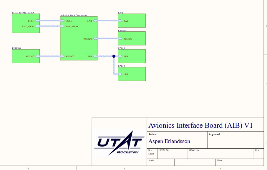
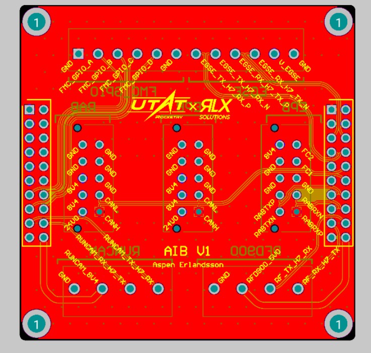
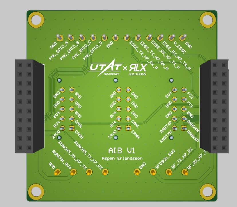
Avionics Interface Board V1
The central hub/motherboard for the new vertical stacking avionics architecture.
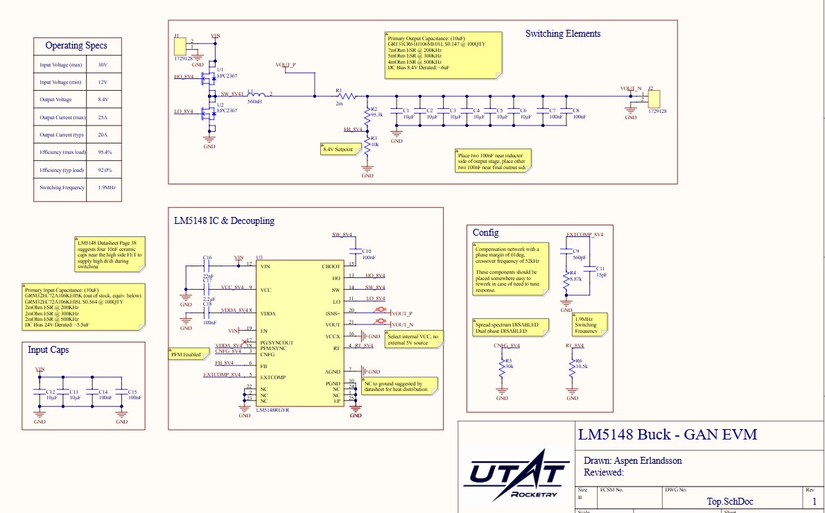
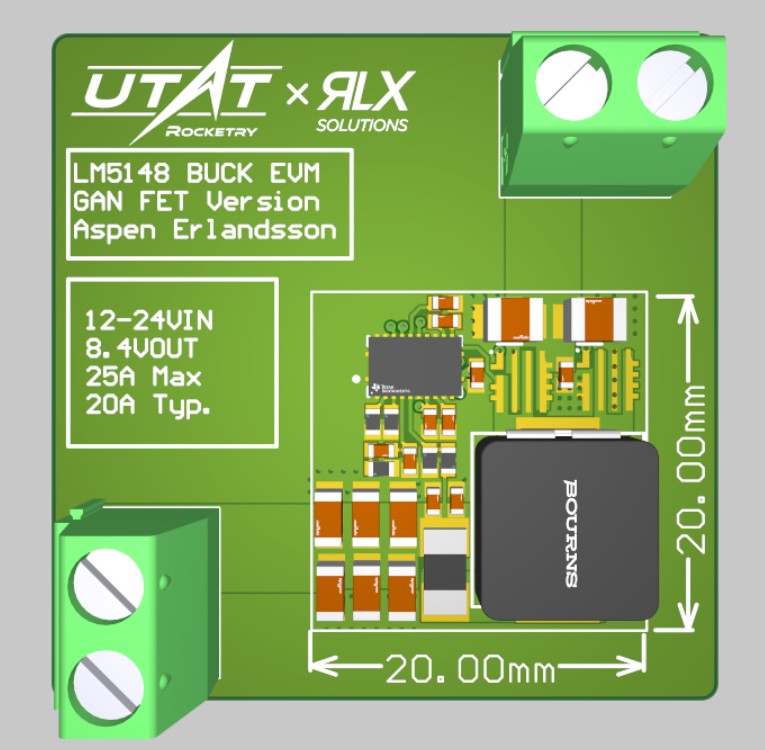
GaN Buck EVM
Advanced buck converter based on LM5148 using Gallium Nitride (GaN) FETs for ultra-low switching and conduction losses.
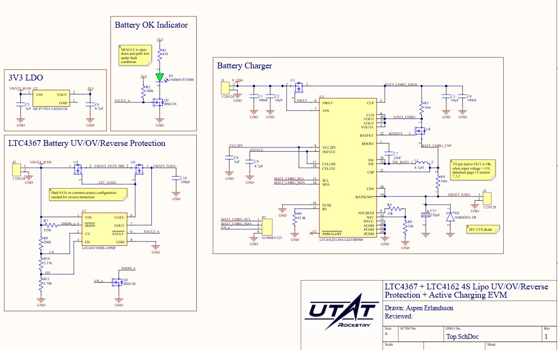
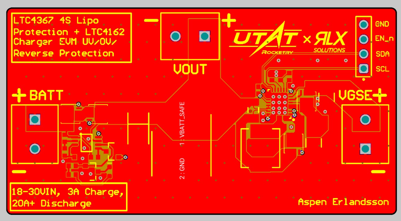
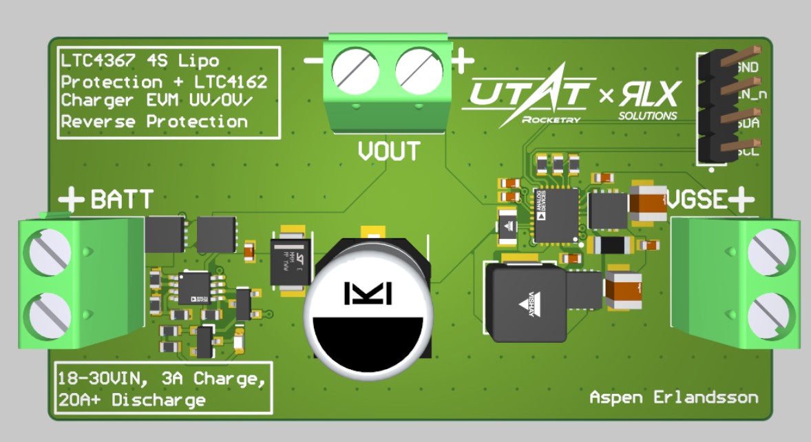
LiPo Charger EVM
Active battery charging and protection test circuit. Enables the rocket to run on internal power while slowly charging from ground, avoiding inductive penalties of long power lines.
Synapse Node Prototype
Baseline prototype for next-gen distributed-node ground support equipment.
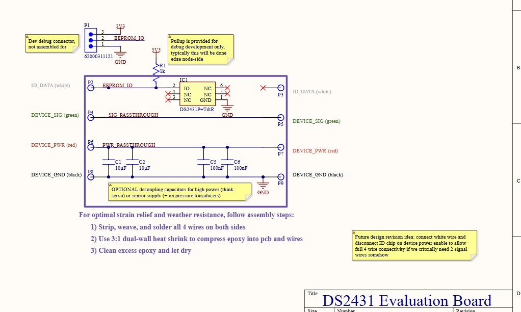
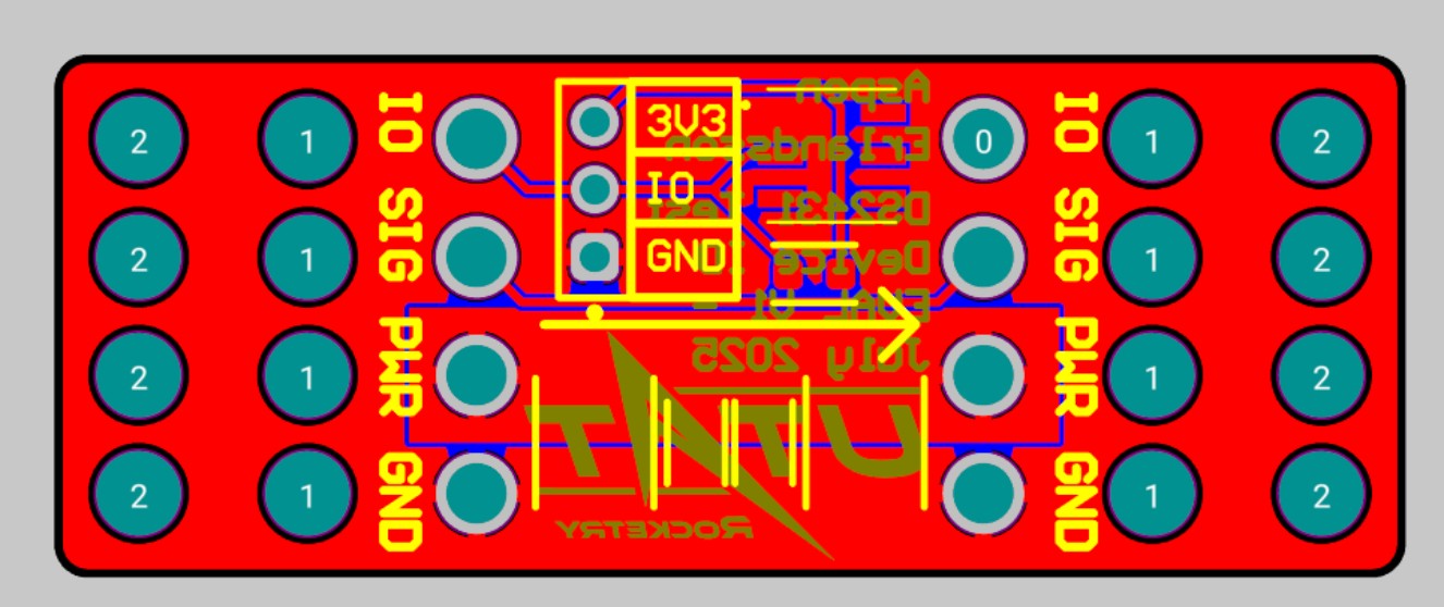
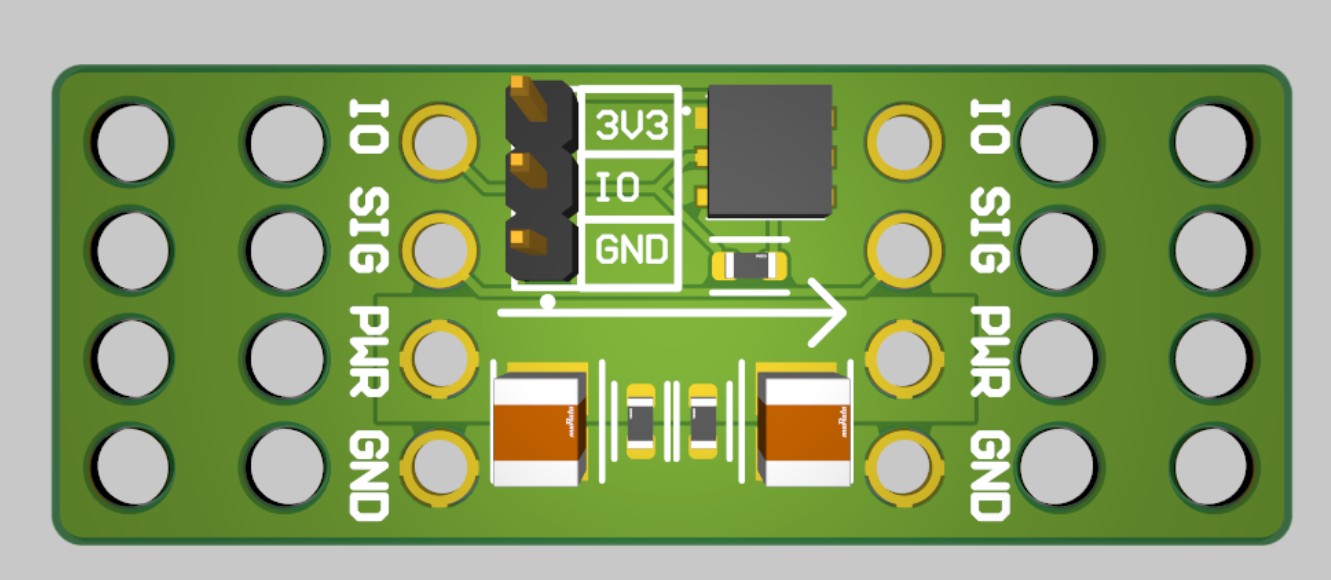
Wire-Through EEPROM Test
Test board for single-wire EEPROM device ID and mechanical strength of wire-through-PCB connections.
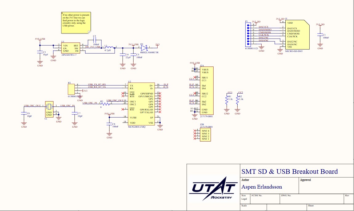
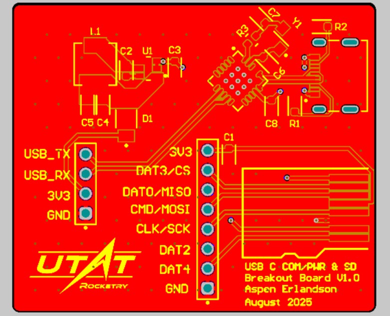
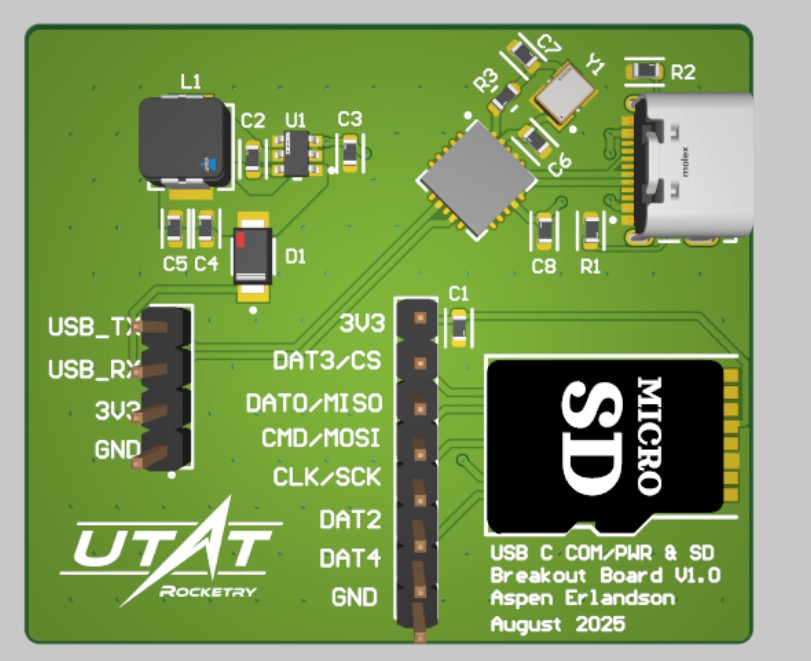
SD & USB Breakout
Test board for direct surface-mount SD cards and USBC serial interfaces. Merged into FMCV2 to accelerate timelines.
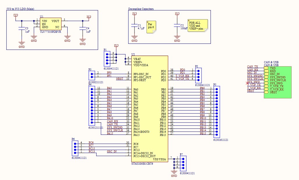
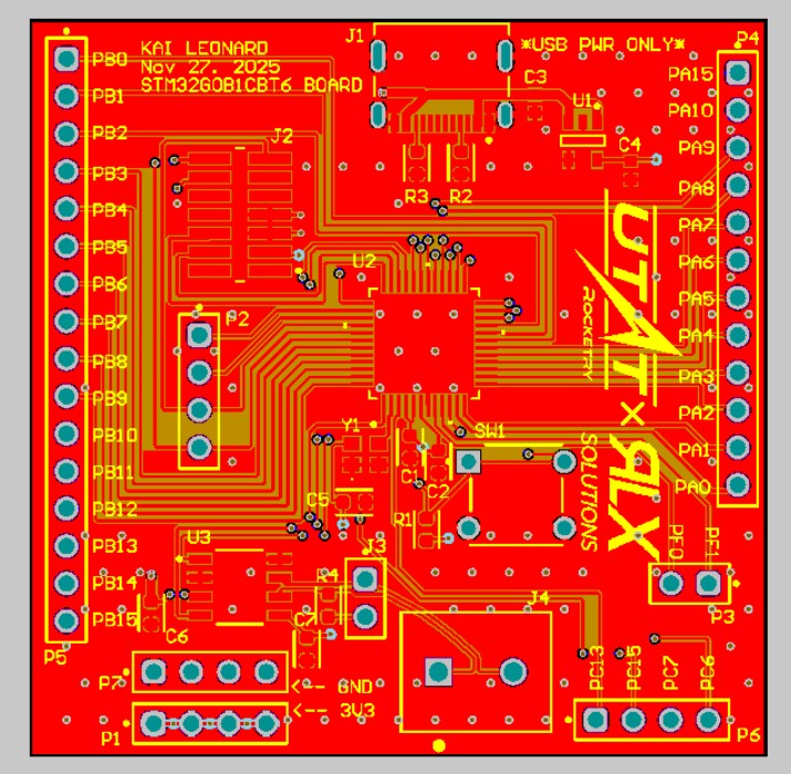
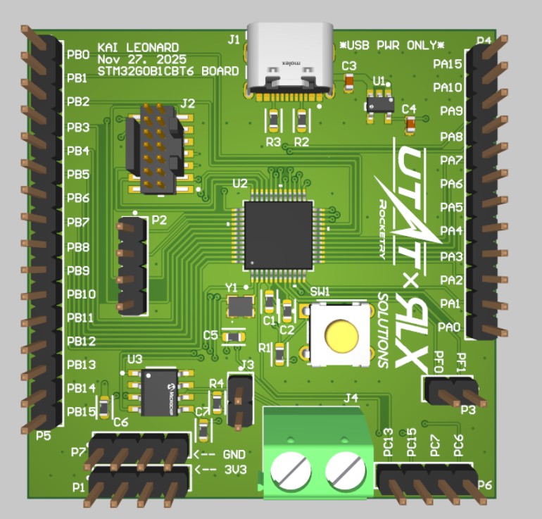
STM32G0 Breakout
Hardware baseline for the STM32G0 microcontroller selected for the EPB and other compact boards.
Video Decoding Breakout
Integrates an STM32H7 and ADV7180WBCP32Z to convert analog video from a Runcam Split4 V2 into a digital stream for compression and RF transmission.
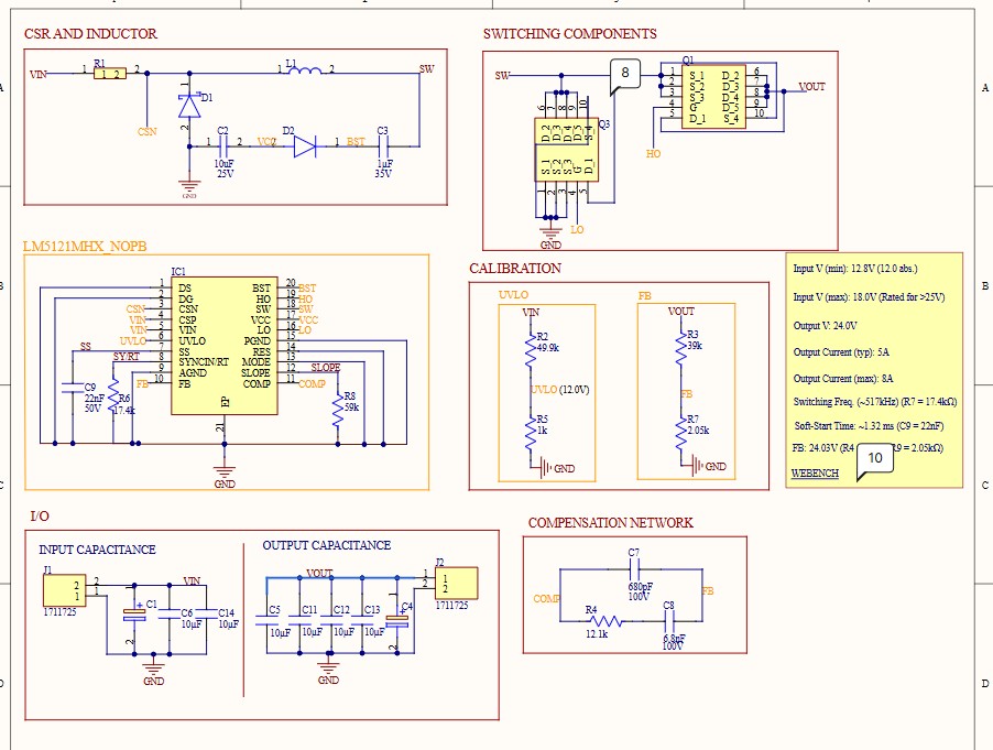
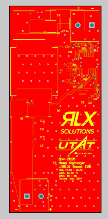
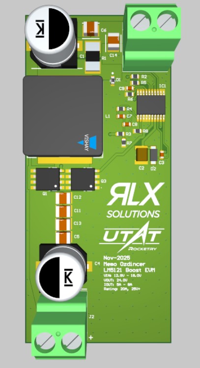
LM5121MH Sync Boost EVM
Updated synchronous boost converter targeting 12-18Vin and 24V/8A out. Aims for better thermal performance and smaller footprint.
LM3150MH Buck V1
Design iteration exploring parallel high-side and low-side FETs for thermal distribution. Superseded by better controller selection.

LM3150MH Buck V2
Alternative rapid-iteration layout for the LM3150 controller.
Buck Converter Prototype
First buck converter design attempt. Provided critical learning on layout and component selection.
LM25118 Boost V0
Initial asynchronous boost attempt. Redesigned before fabrication.
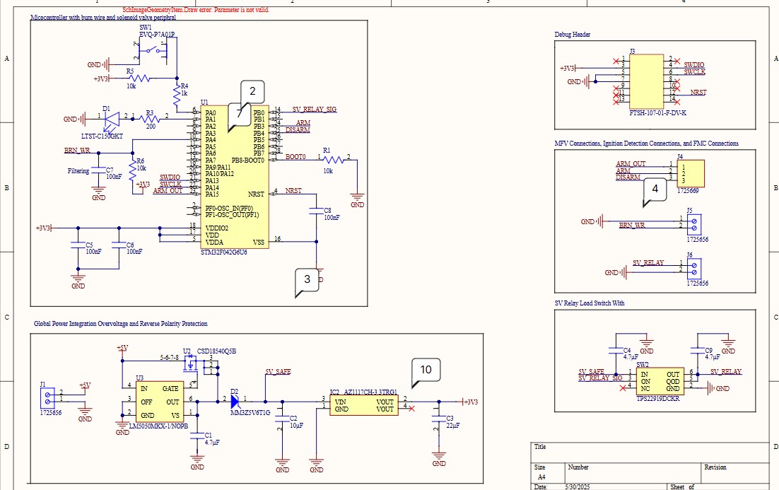
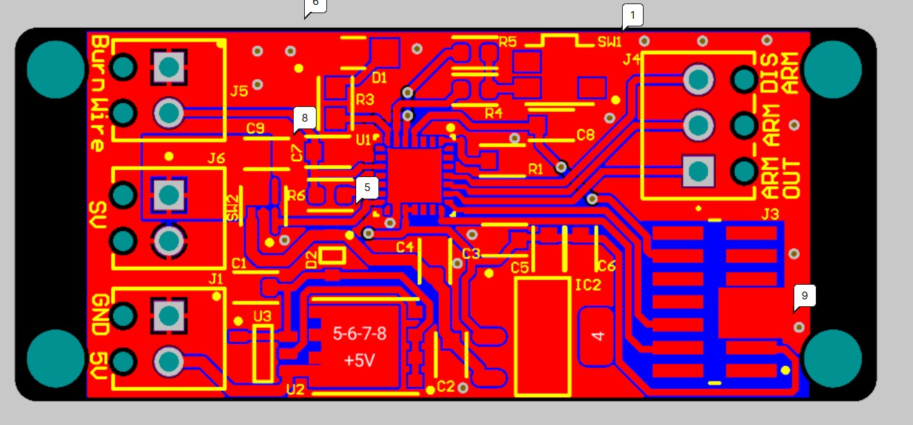
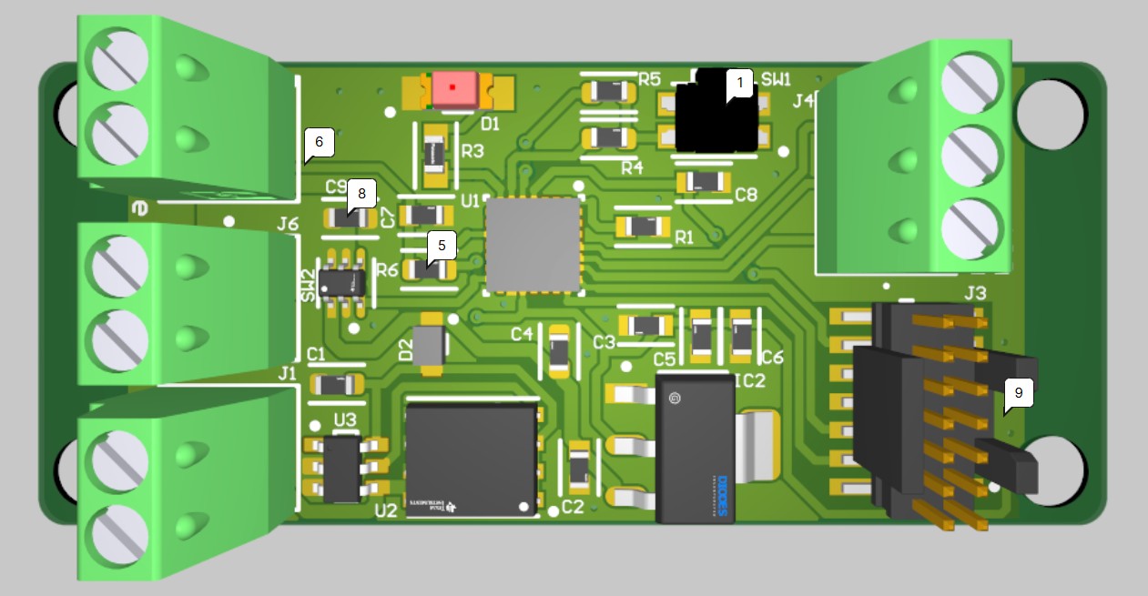
Ignition Management Controller - Vehicle
Dedicated PCB integrating a simple microcontroller which performs the safety critical function of all vehicle-side checks and actuations for the ignition sequence.
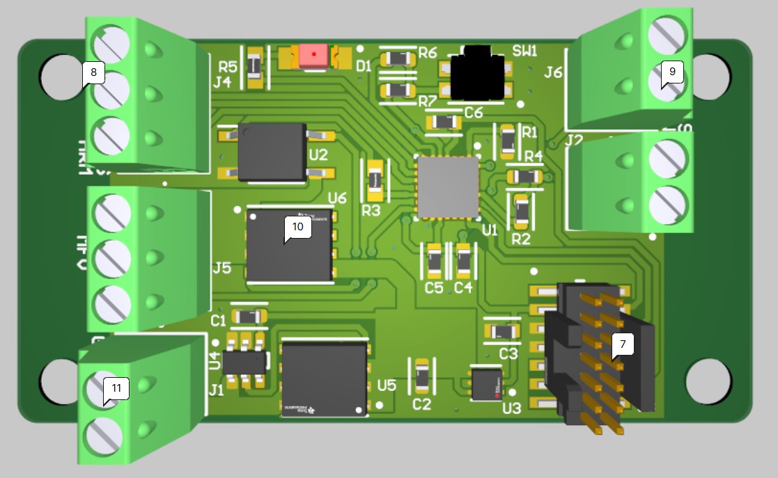
Ignition Management Controller - Ground
Dedicated PCB handling operations on the ground side, interfacing with electronic ground support equipment (EGSE) and detecting ignitor heat using a burn-wire.
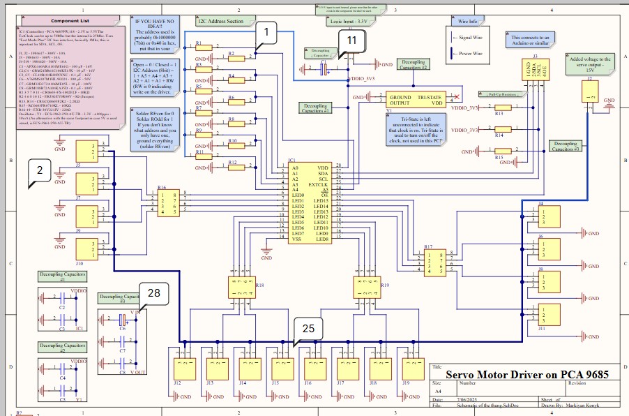
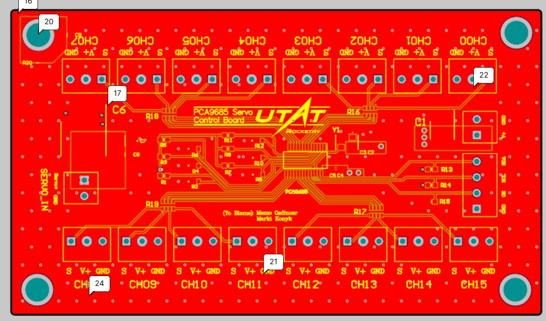
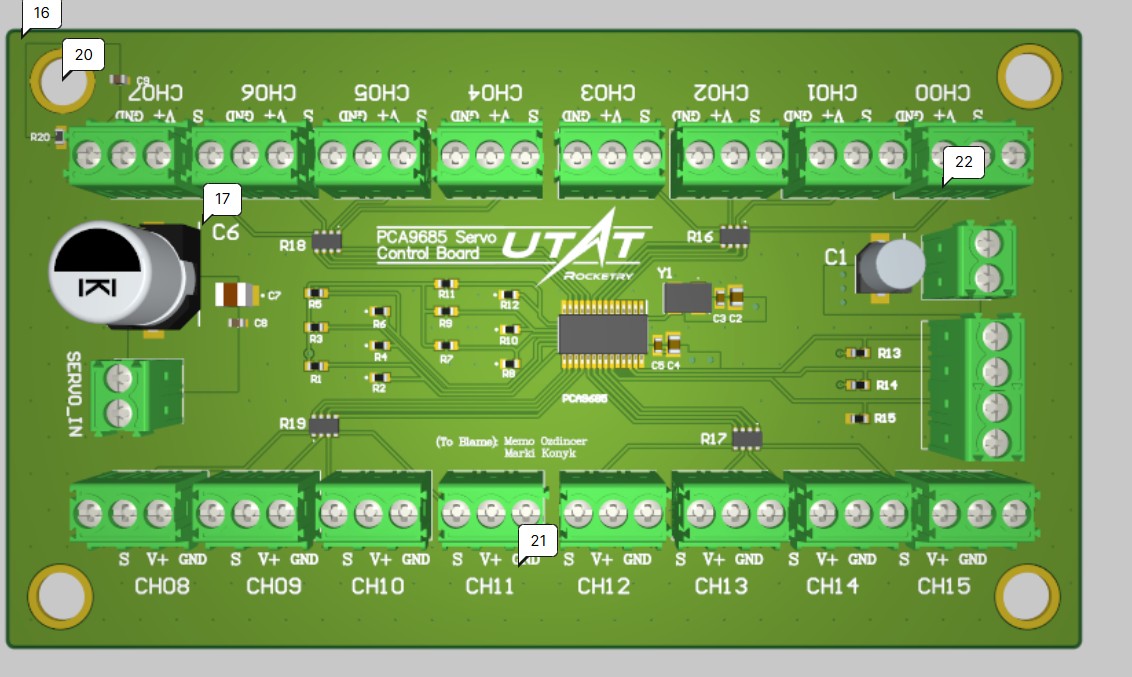
PCA9685 Servo Driver Breakout
Designed for harsh ground support environments with screw terminals and a solid onboard crystal clock. The design was fully completed and passed review, but production was suspended in favor of the new distributed Synapse architecture.
Leadership, Mentoring, Standardization
Host dedicated 1h+ meetings with the avionics team 2-3 times per week covering general update meetings, weekly worksessions, and dedicated testing/assembly campaigns. That's in addition to the admin/inter-lead meetings that also happen 1-2 times per week, plus the weekend propulsion worksessions where we do engine tests and I support the avionics aspect.
Avionics has not been this big or complex on UTAT Rocketry, ever before. Last year before I joined, I was told they made 2-3 small PCBs to support the simpler solid rocket and hybrid rocket projects. Most components were purchased off-the-shelf, and the few PCBs they did make were limited in scope, not using standardized components, and not well documented. Stepping into the lead position I focused heavily on not only building up the team's skills, but also making frameworks, standards, and detailed documentation on the current system so future leads and members can easily pick up where I left off and continue development rather than spending months trying to figure out what we did, or worse giving up and starting over. Some high level goals I enforce are:
- Design reviews are always a team-wide activity, I go over my thoughts on the board primarily as the lead, but everyone has the opportunity to share feedback or ideas as well. This keeps the team engaged, and lets people learn passively from projects they aren't directly involved in.
- Standardized shared Altium parts library with defined processes for adding new parts, including a team-wide common set of footprints/symbols for passives (0603 resistors all have the same one, for example). Enforcing consistency in this way makes it easy to read schematics, have confidence from a DFM perspective, and reduces effort for designers thanks to reuse.
- Common schematic and PCB rules template for all new projects to further aid standardization and ease of design, make it harder for mistakes to get past review through DRC rules.
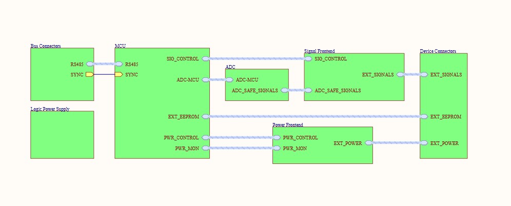
- Complex boards require a system diagram in draw.io before serious design takes place. This makes it easy to review the "idea" of the board before rigorously selecting parts, and later serves as pre-made documentation for design reports and internal resources.
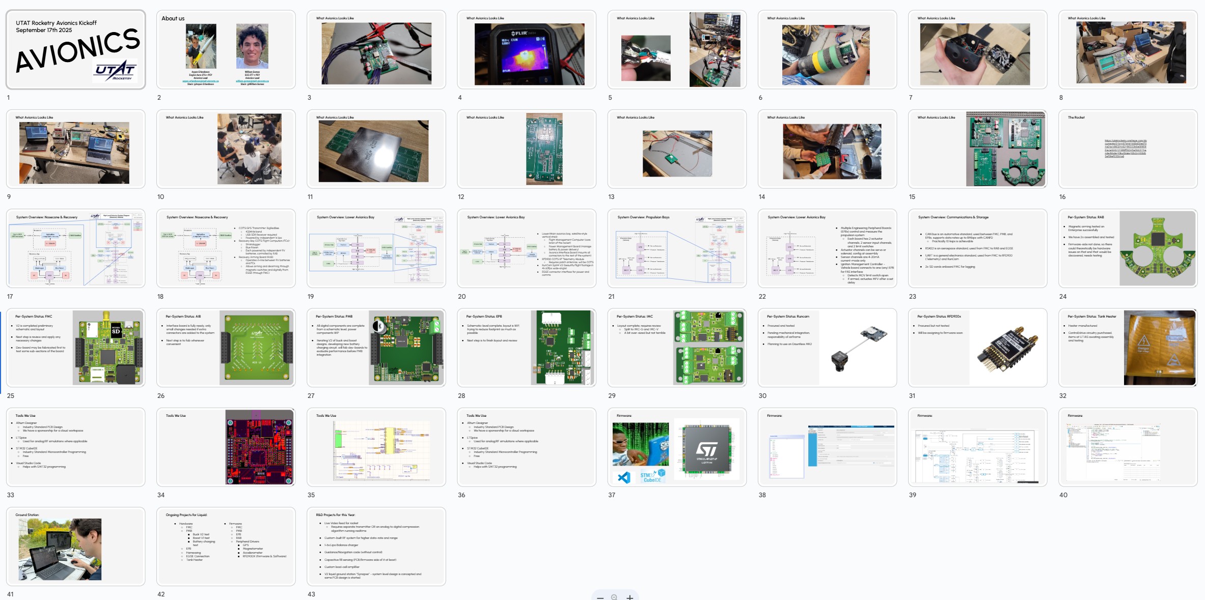
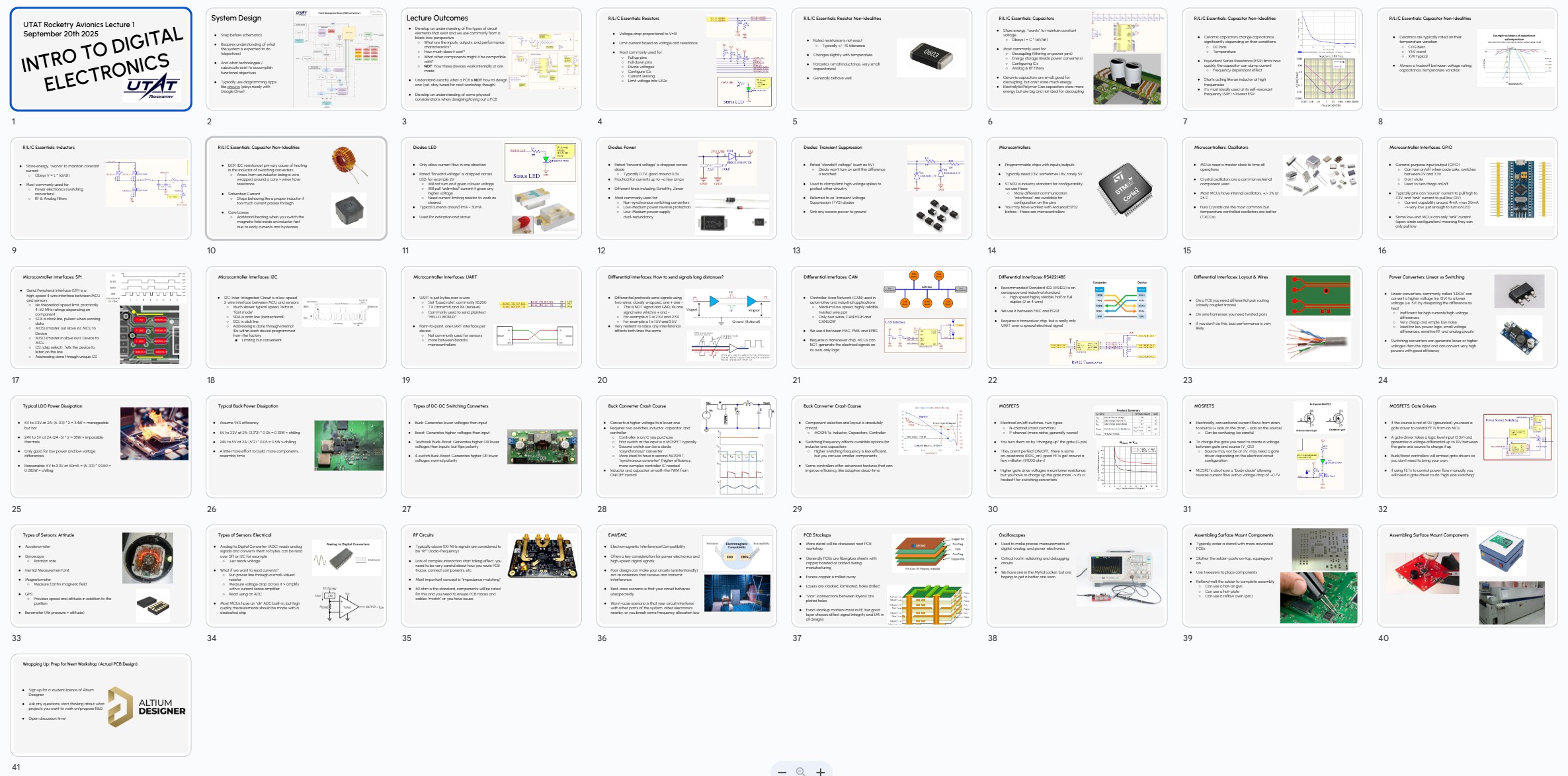
In support of the new influx of members at the beginning of the school year, I hosted multiple workshops to get students up to speed within our highly technical team. For onboarding alone I hosted the hardware section of our Introduction to Avionics kickoff (my co-lead William G. hosted the firmware section). I presented the following to 30+ new members:
After the kickoff, William hosted the firmware lectures, while I hosted hardware. First I created and presented "Hardware Lecture 1: Intro to Digital Electronics". I recorded the full lecture and posted it on YouTube, as linked below:
Then, I hosted a complete Intro to Altium Designer tutorial making an LED project PCB. After the session, I recorded a dedicated video for those who missed it and posted it on my YouTube channel:
Finally, I hosted an in-person-only hands-on workshop where I showed people how to design their own mini rocket flight computers using an STM32F4, IMU sensor, and USB interface. It was based on the part choices in my STM32F4 test board which is pictured below.
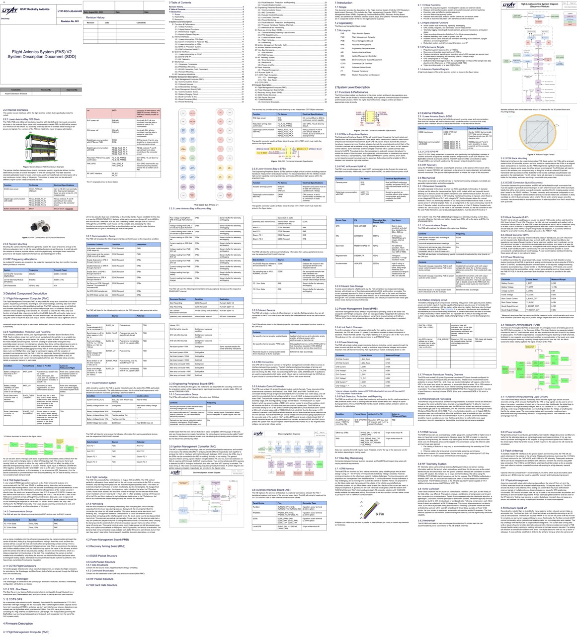
To support continuity of knowledge, faster onboarding, and a centralized source of truth for system interfaces, I solo-developed the Flight Avionics System (FAS) System Design Description (SDD) before the new influx of students. The SDD is a living document with 38 pages currently, and it describes all aspects of the (flight) avionics, how they interface with each other, and importantly how they interface with the other rocket systems (recovery, propulsion, airframe). The SDD content is semi-proprietary within the team, so I will not share the full document here, but a screenshot of all pages in a grid layout gives an idea of the content and structure:
Team Development
I have represented the team at multiple events including:
- UTAT Rocketry Showcase, 2024
- UTAT Rocketry Showcase, 2025
- Engineering Clubs Fair, 2025
- Computer Science Clubs Fair, 2025
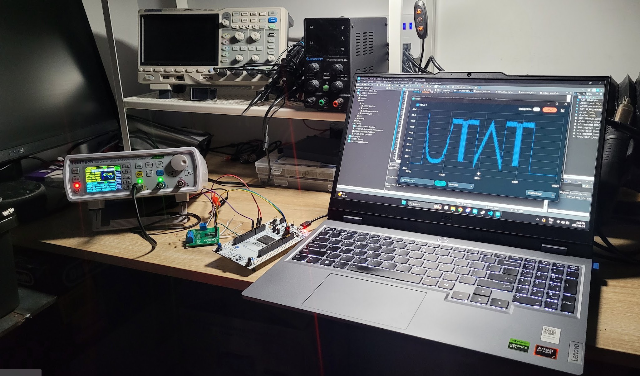
I brought a demo of our ADC driver (written by William G.) to our Showcase events, using my personal function generator I draw the text "UTAT" with voltage, and use our custom ADC board and custom driver with an STM32-NUCLEO to send those voltage to a computer. The values are then plotted on a voltage-time graph to reveal the text, it usually catches the eye of ECE students.
During these events I focused on demonstrating our systems, explaining our approaches to design, and inspiring new students about engineering (in general), and joining our team. I also spoke with sponsors including a representative from RLX Solutions.
After sharing our mission and design plan for this coming year, the representative from RLX was so impressed that he offered to sponsor the fabrication of all our PCBs for the new rocket - a huge win for our team. Many thanks to RLX for their continued support of our advanced projects.
Testing, Debugging, & Team-wide Support
In addition to design and leadership, I spearhead bench testing, thermal/electrical validation, and firmware integration including writing firmware myself.
This testing includes:
- Switching converter (Buck, Boost) stability, and electrical performance
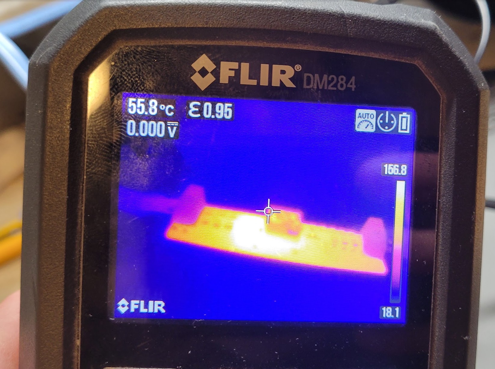
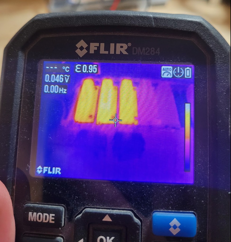
- Thermal testing of power systems
- Hardware edge-case testing including under voltage, over voltage, short-circuit load
- Analog measurement testing and debugging such as current monitoring, voltage monitoring, and pressure transducer readings
- Debugging design errors at a hardware-level, implementing temporary fixes so firmware development can continue (fly-wires, desoldering components, scraping traces, etc)
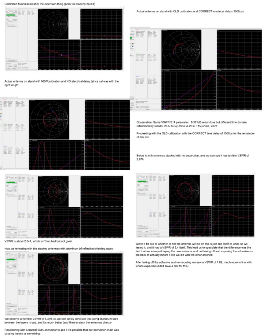
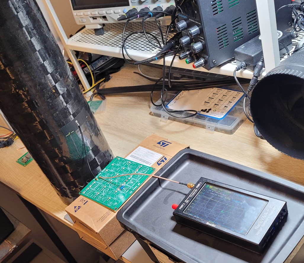
- Patch antenna RF performance evaluation including scattering parameters, and radiation efficiency when placed on nonconventional surfaces such as carbon fiber
- Mechanical fit into the airframe, internal tolerancing, clearances for components
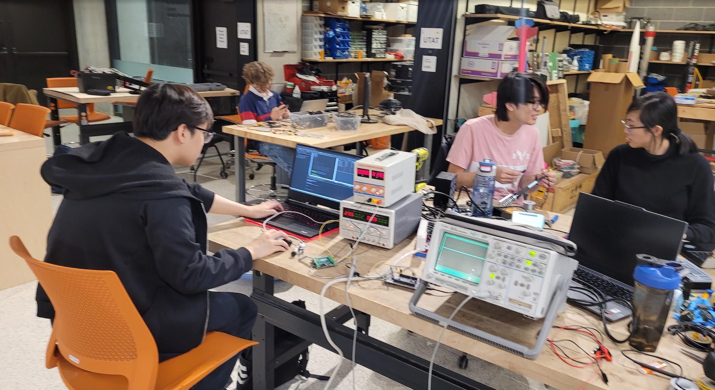
I used the following tools often:
- Oscilloscope (4 channel, 0-100MHz personal most often, and 2 channel 0-100Mhz team-shared sometimes)
- Multimeter
- FLIR thermal imaging camera
- Programmable power supply
- Function generator (2 channel, 0-60MHz personal)
- Vector Network Analyzer (0-3GHz personal)
- Spectrum Analyzer (0-8GHz personal)
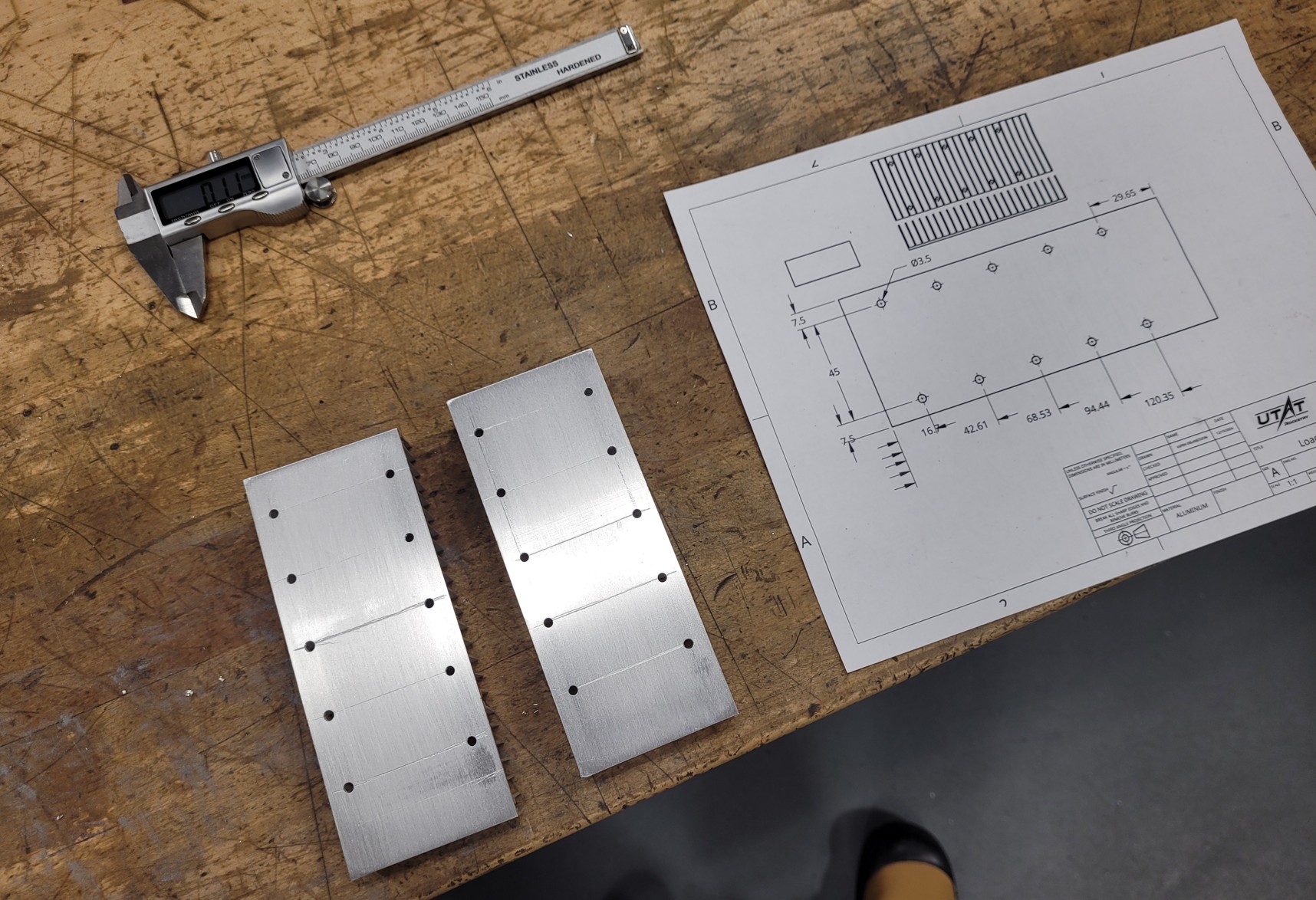
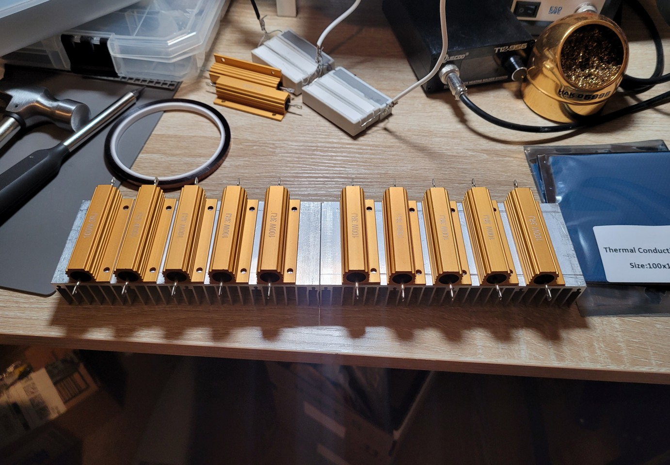
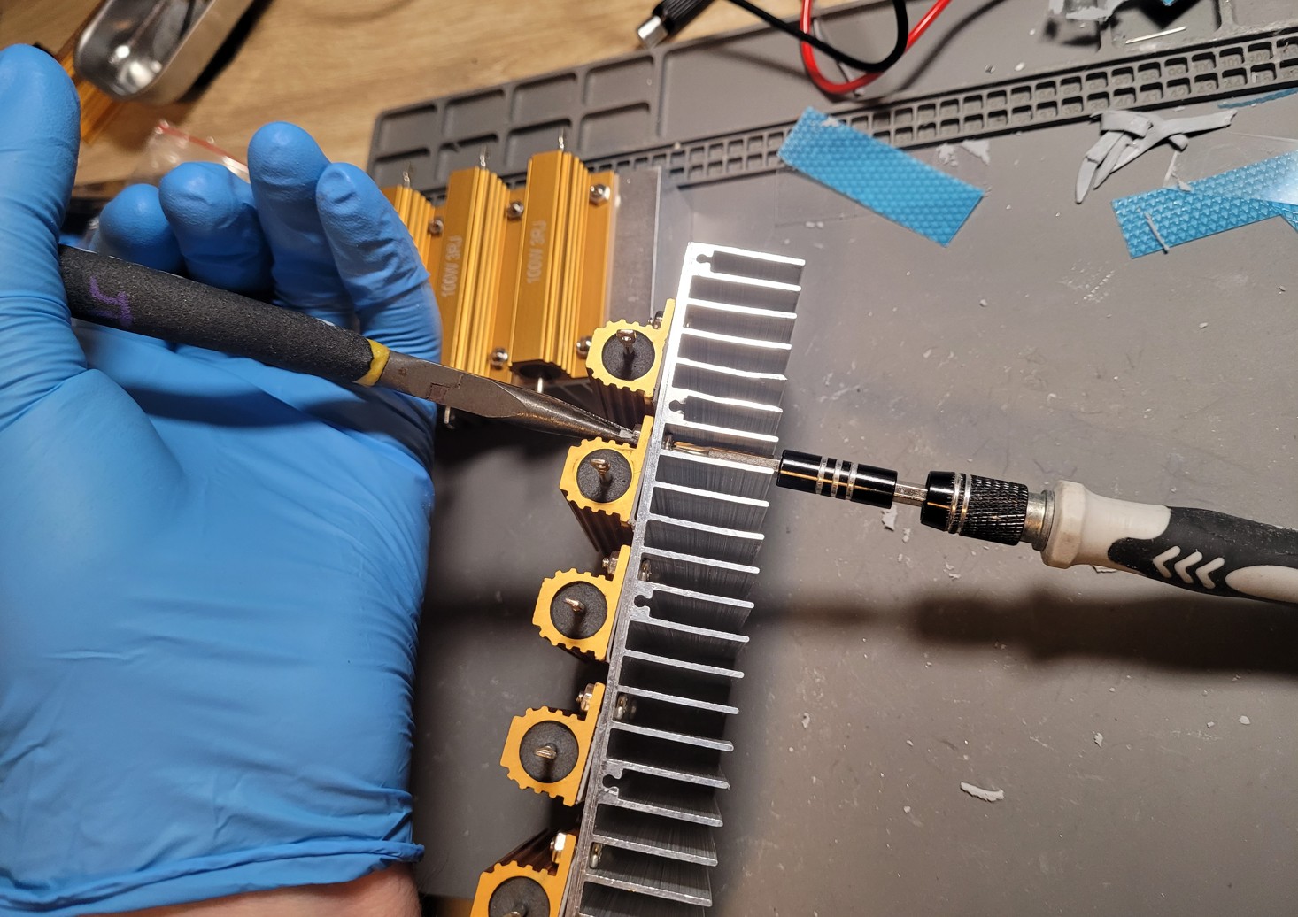
To support testing of high power electronics (100W+) I built my own adjustable load with ceramic resistors, a heat-sink, and manual machining for better thermal contact and rigid mounting. The load bank can support hundreds of watts continuously without overheating (with proper airflow), and was solo-built by me.
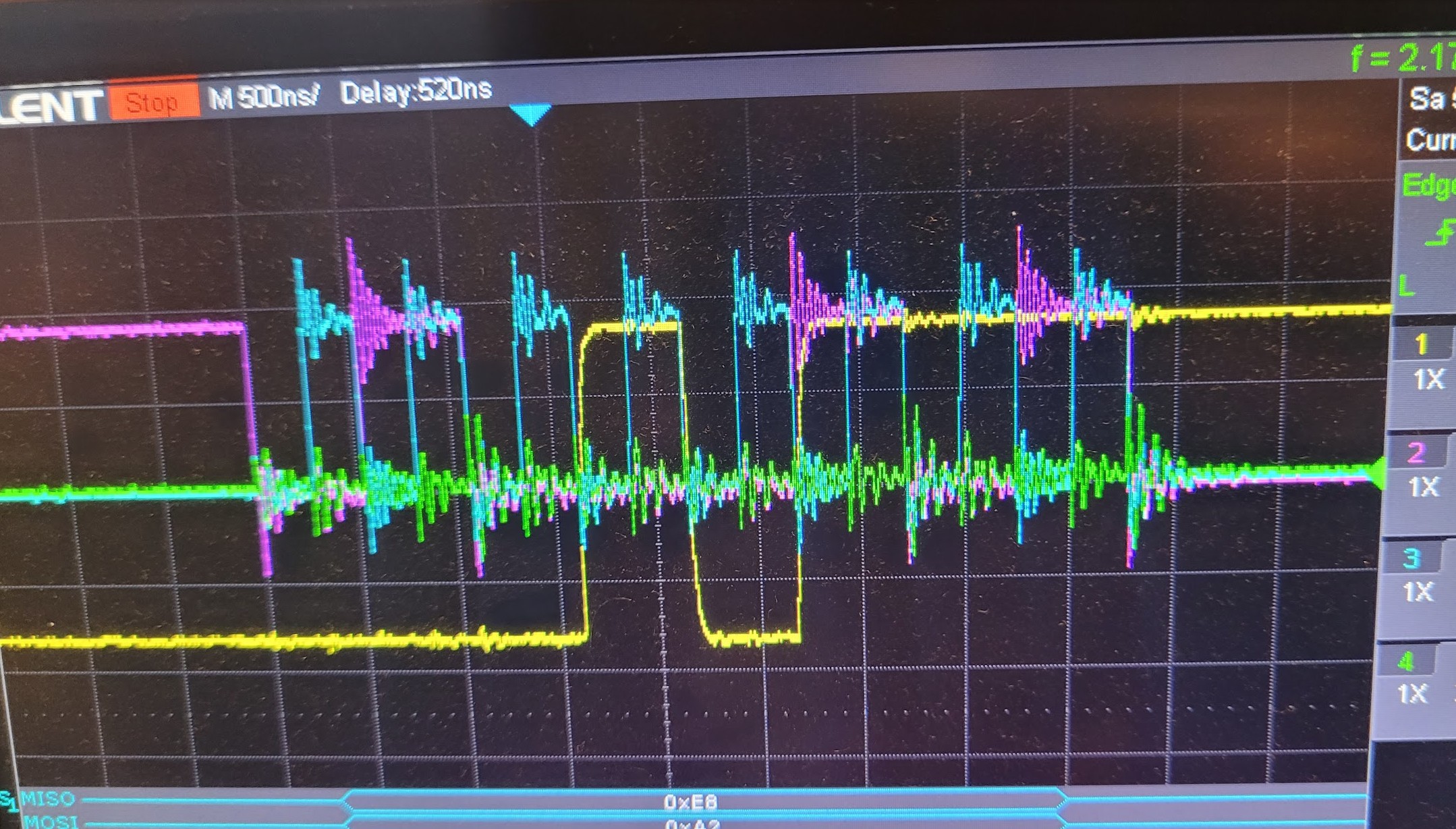
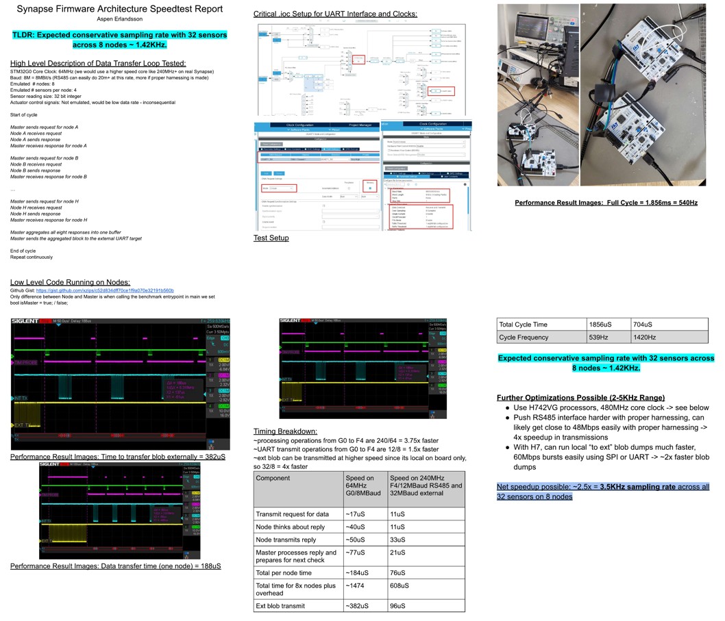
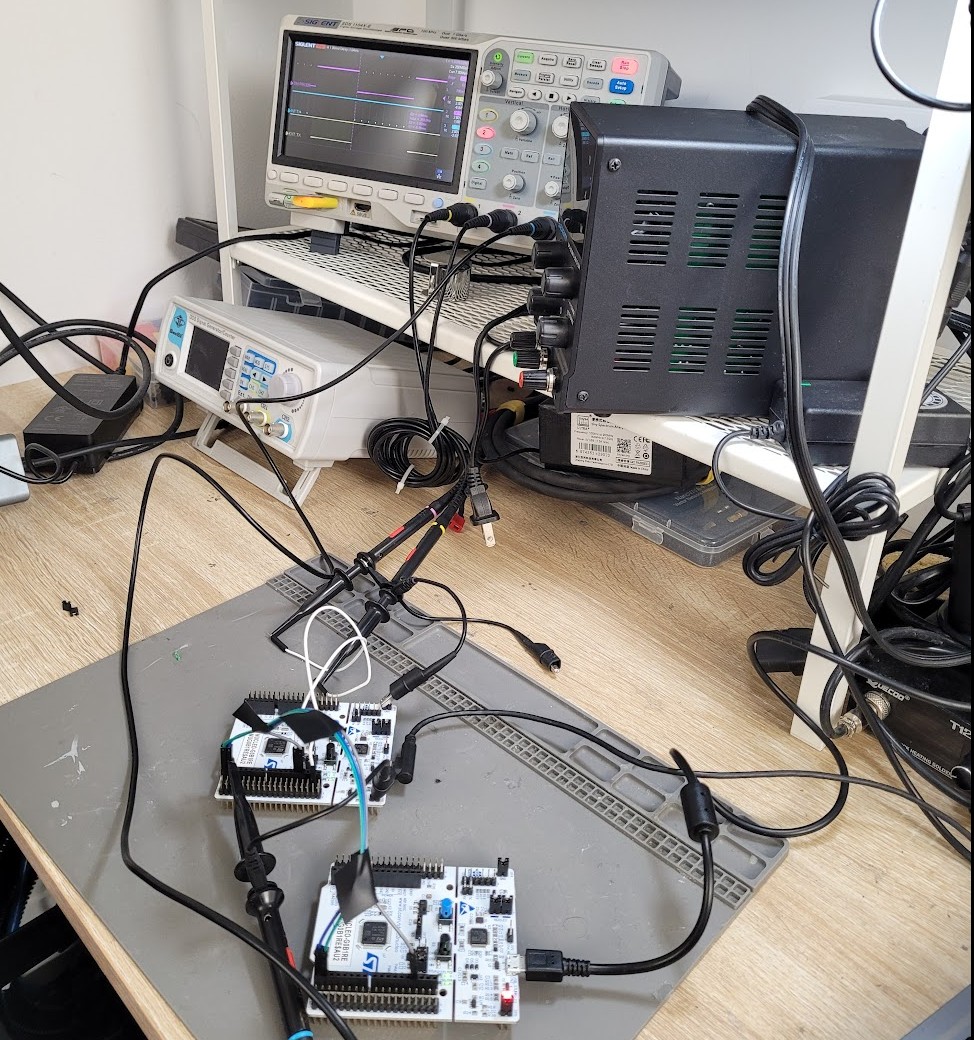
I also performed numerous broader system-level/integration testing activities. Two highlights include evaluating patch antenna performance when mounted to a conductive material structure (carbon fiber tube), and testing the maximum data exchange rate between two STM32s over UART under specific constraints applicable to our Synapse node-based ground station project. Below are screenshots of the testing results.
In conclusion, UTAT has given, and continues to give me broad exposure to developing and testing all aspects of embedded systems from hardware to firmware design and testing.